Cofferdam device for controlling waste working face in landfill

A technology for working surface and landfill site, which is applied in the field of cofferdam device to control the garbage working surface of landfill site, which can solve the problems of large exposed area of ​​slope, large area of ​​garbage paving, and aggravation, so as to reduce the exposed area of ​​operation, Optimized separation of rain and sewage, and the effect of reducing foul odor

Active Publication Date: 2015-12-16
SHANGHAI LAOGANG WASTE DISPOSAL CO LTD
View PDF5 Cites 0 Cited by
  • Summary
  • Abstract
  • Description
  • Claims
  • Application Information

AI Technical Summary

Problems solved by technology

[0002] At present, in the process of garbage paving and compaction, the working surface is completely open, and the four sides are not restricted. Due to the natural sliding of the garbage, the slope of the landfill is relatively slow, so that the exposed area of ​​the side slope of the pile is too large , is the source of severe stench and odor on the landfill operation surface; and due to the natural sliding of the garbage, the pile cannot be covered in time, so that the surface of the pile cannot be completely separated from rain and sewage; in addition, due to the landfill operation surface The strength of the surrounding piles is low, and the compactor cannot drive on the edge of the working surface, which makes the garbage paving area too large, cannot effectively control the working surface area, and aggravates the emission of stench

Method used


Image

  • Cofferdam device for controlling waste working face in landfill
  • Cofferdam device for controlling waste working face in landfill

Examples


Embodiment Construction

[0015] The preferred embodiments of the present invention are given below in conjunction with the accompanying drawings to describe the technical solution of the present invention in detail.

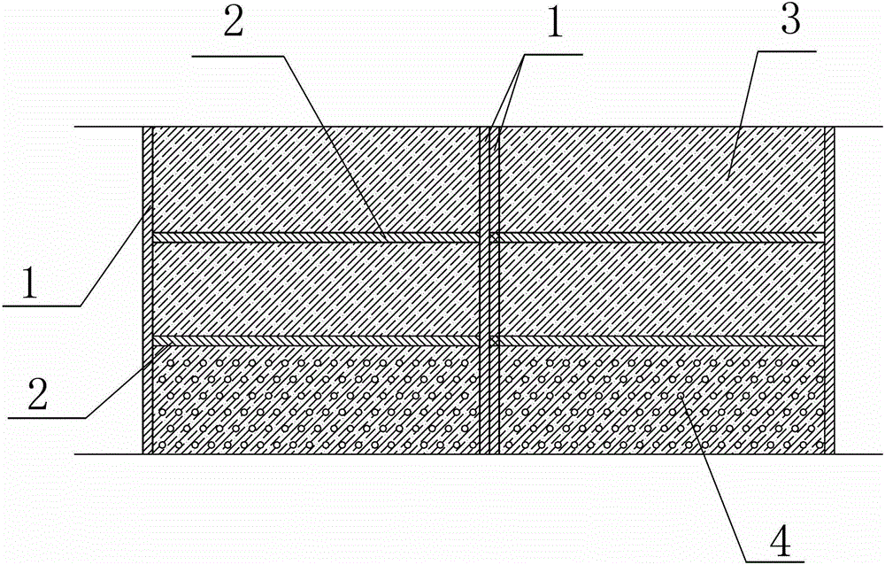
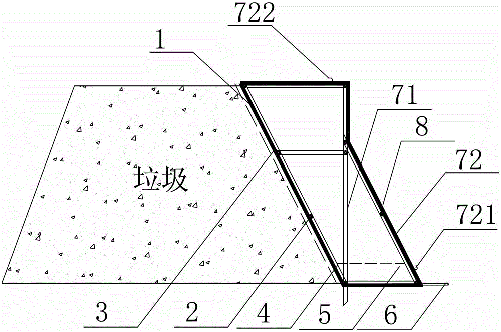
[0016] figure 1 It is a structural schematic diagram of the present invention, figure 2 for in figure 1 The left side view after adding the support rod vertical to the ground and the oblique support rod inserted into the ground. Such as Figure 1-2 Shown: the vertical support column 1 and the horizontal support column 2 of the present invention, the vertical support column 1 and the horizontal support column 2 are welded into several "mesh"-shaped frames, the surface of the frame is welded with a baffle plate 3, and the baffle plate 3 The part close to the ground is the perforated section 4 with leaking holes on the surface, and a sewage tank 5 is installed at the bottom of the perforated section 4, and the sewage tank 5 is a groove made of a plastic plate, with holes connected to th...


PUM


Abstract

The invention relates to a cofferdam device for controlling a landfill garbage working plane. The cofferdam device comprises vertical supporting columns and transverse supporting columns. The vertical supporting columns and the transverse supporting columns are welded into a plurality of frames which are in a shape like the Chinese character 'mu', the surfaces of the frames are welded with baffles, the parts, close to the ground, of the baffles are tapping sections with the surfaces provided with water leakage holes, sewage grooves are formed below the tapping sections are respectively, the sewage grooves are grooves made of plastic plates, holes are formed in the grooves and are connected with pipes for draining waste water, the outside portions of the frames are supported by supporting rods made of metal materials, each supporting rod comprises a supporting rod body perpendicular to the ground, the exteriors of the supporting rod bodies perpendicular to the ground are welded with inclined supporting rods inserted into the ground in an inclined mode, and aluminum plastic panels are arranged on the outer sides of the inclined supporting rods to separate the whole cofferdam device and the garbage working plane from the outside. The garbage stack slope can be made to conform to the proportion of 1:1.5, the working exposed area can be obviously reduced, the working plane can be effectively controlled, the optimization of rain and dirt diverting can be achieved by combining a mulching film, and the appearance is clean in the garbage operation process.

Description

technical field [0001] The invention relates to a cofferdam device, in particular to a cofferdam device for controlling the garbage working surface of a landfill site by adopting a cofferdam construction method of an assembled light steel structure with a forward tilt and a rear support. Background technique [0002] At present, in the process of garbage paving and compaction, the working surface is completely open, and the four sides are not restricted. Due to the natural sliding of the garbage, the slope of the landfill is relatively slow, so that the exposed area of ​​the side slope of the pile is too large , is the source of severe stench and odor on the landfill operation surface; and due to the natural sliding of the garbage, the pile cannot be covered in time, so that the surface of the pile cannot be completely separated from rain and sewage; in addition, due to the landfill operation surface The strength of the surrounding piles is low, and the compactor cannot driv...

Claims


Application Information

Patent Timeline
Patent Type & Authority Patents(China)
IPC IPC(8): E02D29/02
Inventor 黄仁华施韶峰周家浩周海燕张美兰苏冬云黄皇
Owner SHANGHAI LAOGANG WASTE DISPOSAL CO LTD
Why Eureka
Try Eureka