
A motor reciprocating drive linear pumping machine

A reciprocating drive and drainage technology, which is applied in the direction of production fluid, earthwork drilling, wellbore/well components, etc., can solve the problems of adjustment, maintenance and repair of beam pumping units, low pumping unit system efficiency, and installation costs. The problem of large space is needed to achieve the effect of easy maintenance and repair, small wellhead operation area, and improved mechanical efficiency and system efficiency.

Inactive Publication Date: 2016-03-02
DINKUM TIANJIN
View PDF5 Cites 2 Cited by
  • Summary
  • Abstract
  • Description
  • Claims
  • Application Information

AI Technical Summary

Problems solved by technology

However, the beam pumping unit with mature technology also has its own relatively serious defects that are difficult to overcome: first, the large volume of the pumping unit itself leads to large metal consumption, large installation space, high manufacturing cost, and inconvenient transportation and installation. ; Second, due to the need for a relatively long crank radius, the crank radius is proportional to the reciprocating stroke of the sucker rod, and the end of the donkey head of the beam is generally smaller than the end of the beam axis, and the crank balance weight and the beam balance weight consume their own motion The inertial force, moment of inertia, component force of connecting rod movement, leverage force and the power consumed in the process of its own transmission account for more than 50% of the power of the drive motor, which leads to low efficiency and large power consumption of the pumping unit system. The cost of oil production is high; third, the adjustment, maintenance and repair of beam pumping units are relatively difficult

Method used


Image

  • A motor reciprocating drive linear pumping machine

Examples


Embodiment 1

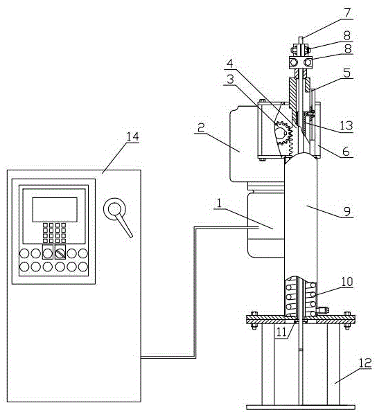
[0013] The motor reciprocating drive linear extraction machine of the present invention mainly comprises control box and extraction machine, and control box comprises control box main body 14, display screen 15, control button 16, and display screen 15 is installed on control box main body 14, and display screen 15 There is a control button 16 on the side, and the extraction machine includes a drive motor 1, a precision reducer 2, a pinion 3, a rack 4, a sliding track 5, a gear box 6, a sucker rod polished rod 7, a fixed clamp 8, and a support cylinder 9 , buffer spring 10, guide copper ring 11, support 12, sleeve pipe 13, drive motor 1 is a three-phase asynchronous induction drive motor 1 controlled by a frequency converter, and is installed and fixed on the lower end of precision reducer 2. The gear transmission mechanism is composed of a pinion 3 and a rack 4 that cooperate with each other. The pinion 3 is directly installed at the output end of the reducer, the rack 4 is i...


PUM


Abstract

The invention provides a motor reciprocating drive linear pumping machine comprising a control box and a pumping device. Control buttons are arranged on the lower side of a display screen. The pumping device comprises a drive motor, a precision reducer and a pinion. A polish rod of a sucker rod penetrates a central hole of a rack and extends out to the upper end surface of the rack. During ascend, the rack drives the sucker rod to move upward from a bottom dead center to finish a travel and reach a top dead center. At the beginning of operation start, a buffer spring at the bottom of a support cylinder releases stored energy to reduce the start current of the drive motor and increase the start torque. During descend, under the effect of the gravity of a load, the rack drives the sucker rod to move downward from the top dead center to finish a travel and reach the bottom dead center; when approaching the bottom dead center, the energy storage buffer spring begins to absorb energy and reduces the impact generated when the rack reaches the bottom dead center. The motor reciprocating drive linear pumping machine is high in efficiency, simple in structure, easy to install and transport, and small in noise, and is especially suitable for cities and regions with complex terrain and inconvenient traffic.

Description

technical field [0001] The invention relates to an oil recovery machine, in particular to a motor reciprocating drive linear extraction machine. Background technique [0002] At present, domestic and foreign oilfield oil production can be roughly divided into two major methods, that is, oil production by rod pumps driven by surface oil production machinery and oil production by submersible rodless pumps in downholes. Rodless pump oil production mainly uses submersible linear drive motor reciprocating pump and electric submersible centrifugal pump for oil production. The efficiency of submersible linear drive motor reciprocating pump is low, so its application range is small; the speed of electric submersible centrifugal pump High, large displacement, but it is difficult to reduce the speed, so it can only be used in oil wells with sufficient fluid supply. It is precisely because of the above defects that the application range of the rodless pump is greatly limited, so the p...

Claims


Application Information

Patent Timeline
IPC IPC(8): E21B43/00
Inventor 张启民
Owner DINKUM TIANJIN
Learn More