Fully CNC Camshaft Milling Machine

A camshaft and milling machine technology, which is applied to milling machine equipment, milling machine equipment details, driving devices, etc., can solve the problems of increasing the processing cost of camshafts, reducing production efficiency, and increasing the area of ​​​​the workshop, saving materials and processing man-hours, The effect of reducing manufacturing costs and reducing work area

Inactive Publication Date: 2011-12-14
胡益萍 +2
View PDF4 Cites 4 Cited by
  • Summary
  • Abstract
  • Description
  • Claims
  • Application Information

AI Technical Summary

Problems solved by technology

But the existing numerical control camshaft milling machine also has the following problems in processing: one is that the existing numerical control camshaft adopts double power head synchronous transmission, and the double power head synchronous transmission is formed by the cross shaft bridge transmission mechanism, and the cross shaft bridge synchronous transmission Although the mechanism can achieve synchronization, its synchronous transmission accuracy is poor, the transmission structure is more complicated, and the manufacturing and installation are troublesome, which increases the manufacturing cost of the milling machine and reduces the production efficiency; The plane range occupied by the front and rear movement of the guide rail is relatively large, which increases the floor area of ​​the workshop; and because the milling head is processed as intermittent cutting, it is affected by the cutting force during the machining process, and the speed of the milling cutter spindle is unbalanced, and the milling cutter spindle will generate Vibration is prone to broaching and tool collision, which not only increases the processing noise and reduces the service life of the milling cutter, but also affects the milling quality. The reserved grinding amount is more, which increases the grinding workload and reduces the grinding efficiency. Increased camshaft machining costs

Method used


Image

  • Fully CNC Camshaft Milling Machine
  • Fully CNC Camshaft Milling Machine
  • Fully CNC Camshaft Milling Machine

Examples


Embodiment Construction

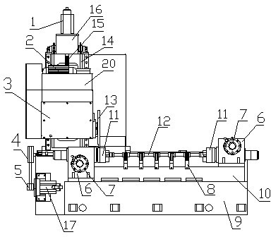
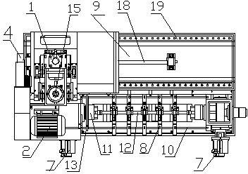
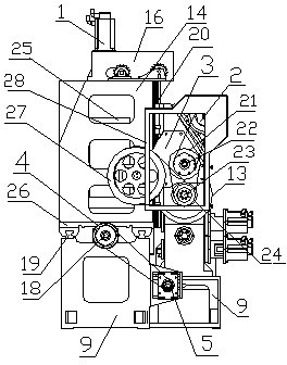
[0014] in figure 1 , figure 2 with image 3 Wherein, the full numerical control camshaft milling machine includes a bed 9, a guide rail plate 10, a guide rail 19, a rotary power head 6, a milling power head 3, a column 14, a main motor 2, a servo motor Ⅰ 7, a servo motor Ⅱ 17, a lifting table 20 and Lifting power head 16, the guide rail plate and the guide rail are arranged side by side on the bed, the guide rail is in the front, the guide rail is in the back, and the two ends of the guide plate are respectively provided with a rotary power head 6, which is directly driven by a servo motor I7, The synchronous transmission is controlled by a full numerical control system. The rotary power head is provided with a hydraulic chuck 11 that can clamp the camshaft 12, and five auxiliary supports 8 that can support the camshaft horizontally are arranged at intervals between the hydraulic chucks. The number of settings can be determined according to the length and size of the camshaft....


PUM


Abstract

The invention discloses a full numerical control camshaft milling machine, which comprises a bed (9), a guide rail plate (10), a guide rail (19), a rotating power head (6), a milling power head (3) and a lifting power head (16), Rotary power heads are respectively arranged at both ends of the guide rail plate, hydraulic chucks (11) are arranged on the rotating power heads, and auxiliary supports (8) are arranged between the hydraulic chucks, and the milling power heads are arranged on the lifting platform, and the lifting platform (20) can move on the column (14). The milling power head includes the milling cutter spindle (23). The column can move left and right on the guide rail (19). An inertial balance wheel (27) or a milling cutter spindle is arranged on the milling cutter spindle. The main shaft is connected with the inertia balance wheel through the driven wheel (24) on the milling cutter main shaft. The milling cutter spindle of the present invention does not generate vibration, which not only reduces the processing noise, prolongs the service life of the milling cutter, but also improves the milling quality, reduces the reserved grinding amount, reduces the grinding workload, improves the processing efficiency, and reduces the Camshaft machining cost.

Description

Technical field [0001] The invention relates to camshaft processing equipment, in particular to a fully numerically controlled camshaft milling machine. Background technique [0002] As we all know, camshaft cam profiles are mostly processed by copying lathes. With the development of science and technology and the improvement of technological quality requirements, most of the camshaft camshaft machining has been replaced by a CNC camshaft milling machine with compact structure, good performance, no profiling, high machining efficiency, and strong applicability. However, the existing CNC camshaft milling machine still has the following problems in processing: First, the existing CNC camshaft adopts dual power head synchronous transmission, which is formed by the cross axle bridge transmission mechanism, and the cross axle bridge synchronous transmission Although the mechanism can achieve synchronization, its synchronization transmission accuracy is poor, the transmission structur...

Claims


Application Information

Patent Timeline
Patent Type & Authority Applications(China)
IPC IPC(8): B23C3/08B23B19/02B23Q5/04B23Q5/22
Inventor 胡益萍彭小明张友华
Owner 胡益萍
Why Eureka
Try Eureka