
Exhaust gas separating tower and exhaust gas separating and recycling system

a technology of exhaust gas and separating tower, which is applied in the direction of dispersed particle separation, separation process, transportation and packaging, etc., can solve the problems of reducing the heat exchanging efficiency, affecting the cooling tower in the prior art, and being expensive and complex. , to achieve the effect of small work area and clean moisture vapor

Active Publication Date: 2015-09-08
NAT DRYING TECH & EQUIP ENG TECH RES CENT
View PDF1 Cites 4 Cited by
  • Summary
  • Abstract
  • Description
  • Claims
  • Application Information

AI Technical Summary

Benefits of technology

The solution achieves clean moisture vapor separation and recycling, preventing impurities from entering other devices and eliminating the need for external heat sources, resulting in a more efficient and compact system.

Problems solved by technology

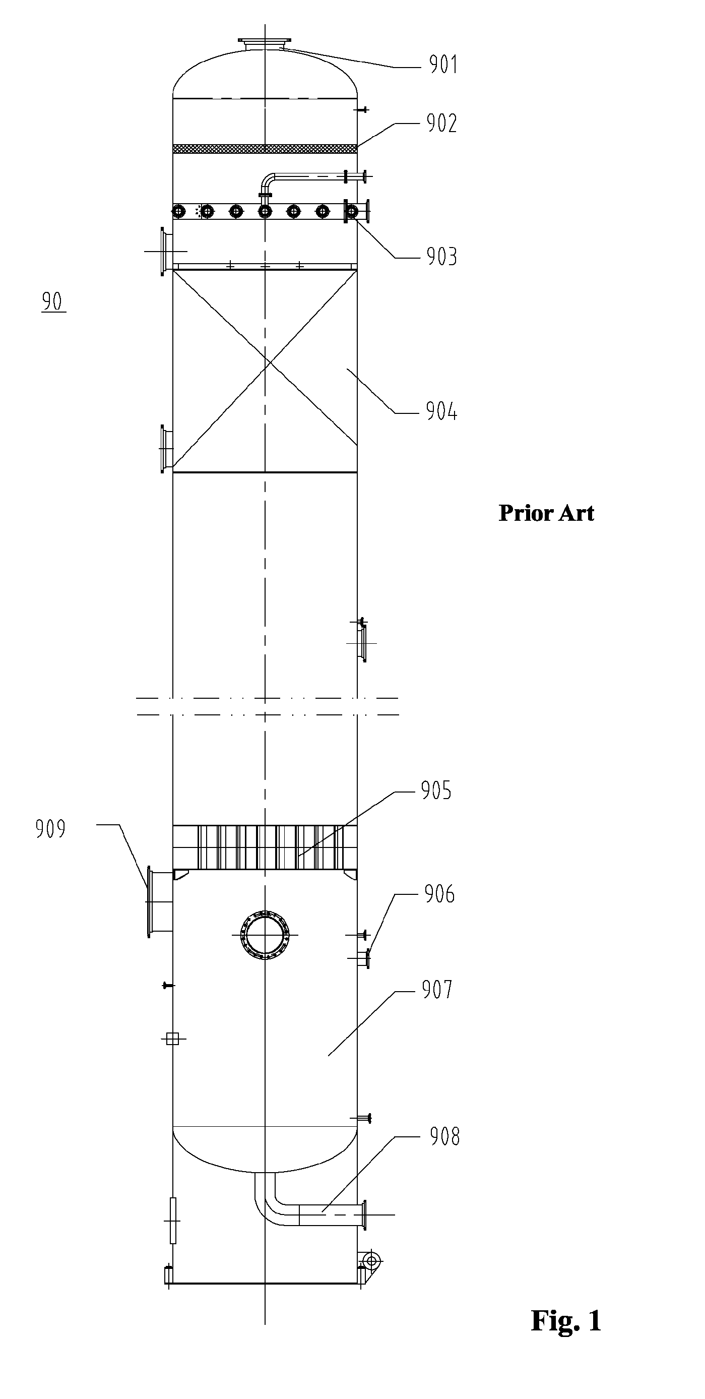
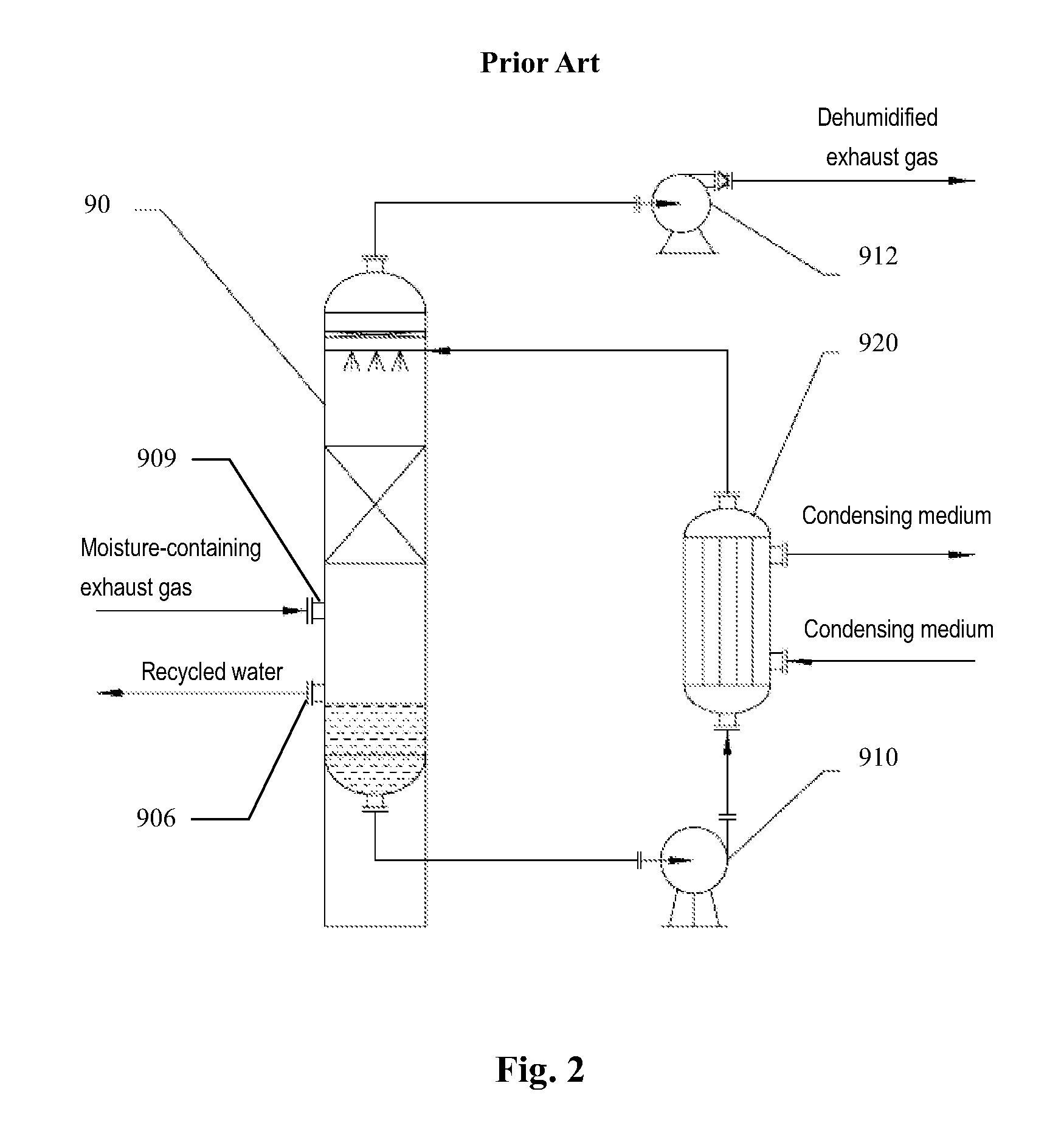
However, such cooling tower in the prior art suffers from the following drawbacks.
Thus, a further liquid-solid separation process is required to be performed on the recycled liquid, which is technically complex and costly.
Furthermore, the dust in the moisture-containing exhaust gas may also enters the circulating cooling liquid, which may block the cooling device during the cooling process for the cooling liquid, and lower the heat exchanging efficiency.

Method used


Image

  • Exhaust gas separating tower and exhaust gas separating and recycling system
  • Exhaust gas separating tower and exhaust gas separating and recycling system
  • Exhaust gas separating tower and exhaust gas separating and recycling system

Examples


Embodiment Construction

[0021]The invention will now be described in details through following illustrative embodiments. However, it should be understood that an element, a structure or a feature in an embodiment can be beneficially incorporated into other embodiments without further recitation.

[0022]Some references, if any, which may include patents, patent applications and various publications, may be cited and discussed in the description of this invention. The citation and / or discussion of such references, if any, is provided merely to clarify the description of the present invention and is not an admission that any such reference is “prior art” to the present invention described herein. All references listed, cited and / or discussed in this specification are incorporated herein by reference in their entireties and to the same extent as if each reference was individually incorporated by reference.

[0023]It should also be understood that “comprises / comprising” when used in the specification is taken to sp...


PUM

PropertyMeasurementUnit
pressureaaaaaaaaaa
temperatureaaaaaaaaaa

Abstract

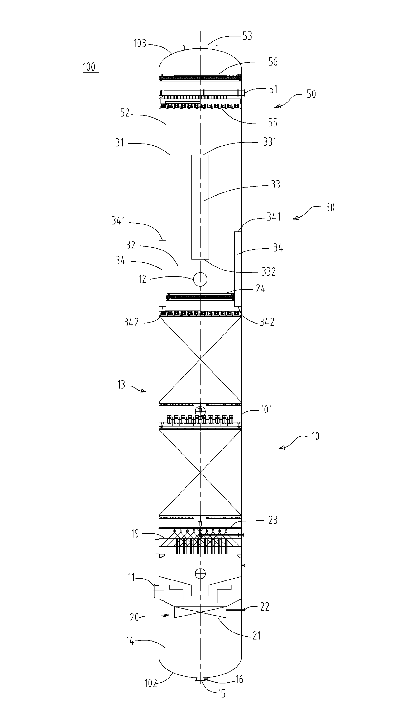
The invention relates to an exhaust gas separating tower, comprising a washing section, a flash-distilling section above the washing section, and a liquid seal means between the flash flash-distilling section and the washing section. The washing section is configured for washing exhaust gas entering the tower with a cooling liquid to at least partially remove solid dust entrained in the exhaust gas, cool the exhaust gas, and condense at least a portion of moisture in the exhaust gas into liquid. The flash-distilling section is configured for flash-distilling the cooling liquid from the washing section to produce a cooled cooling liquid and a cooling liquid vapor. The liquid seal means is configured so that the cooling liquid produced by flash-distillation can enter the washing section through the liquid seal means while the flash-distilling section is in gas-phase isolation from the washing section, wherein a pressure in the flash-distilling section is lower than that in the washing section.

Description

CROSS-REFERENCE TO RELATED APPLICATIONS[0001]The present application claims the priority of Chinese Patent Application No. 201210323017.1 filed on Sep. 4, 2012 and entitled “EXHAUST GAS SEPARATING TOWER”, the entirety of which is incorporated herein by reference.[0002]Some references, if any, which may include patents, patent applications and various publications, may be cited and discussed in the description of this invention. The citation and / or discussion of such references, if any, is provided merely to clarify the description of the present invention and is not an admission that any such reference is “prior art” to the present invention described herein. All references listed, cited and / or discussed in this specification are incorporated herein by reference in their entireties and to the same extent as if each reference was individually incorporated by reference.FIELD OF THE INVENTION[0003]The present invention relates to an exhaust gas separating tower, and particularly to a s...

Claims


Application Information

Patent Timeline
Patent Type & Authority Patents(United States)
IPC IPC(8): B01D47/06B01F3/04B01D47/05B01D47/14
CPCB01D47/05B01D47/06B01D47/14B01F3/04021B01F3/04078B01F3/04468B01F3/04496B01D2247/107B01D2247/14B01F23/213B01F23/214B01F23/2321B01F23/2322
Inventor ZHAO, XULING, YONGGONGDOU, YANSHEN, TAOZHAN, ZHONGFUTAN, YONGPENGZHANG, YAN
Owner NAT DRYING TECH & EQUIP ENG TECH RES CENT
Learn More