Method for reinforcing steel tube truss tubular joint through ring opening sleeves

A technology of intersecting joints and reinforced steel pipes, which is applied in building maintenance, construction, building construction, etc., can solve problems such as weak radial rigidity, affecting structural use space, main pipe cuts or weld damage, etc., to achieve long service life, Good seismic performance, high bearing capacity effect

Active Publication Date: 2014-03-26
湖北杰昆建设工程有限责任公司
View PDF5 Cites 5 Cited by
  • Summary
  • Abstract
  • Description
  • Claims
  • Application Information

AI Technical Summary

Problems solved by technology

[0003] The above methods can be roughly divided into built-in reinforcement method and external reinforcement method. The construction of the built-in reinforcement method is more difficult, and there are cuts or weld damage to the main pipe; the external reinforcement method is relatively simple in construction, but it affects the appearance of the structure and even affects the structure. The use of space; the backing plate reinforcement method can only be welded at the initial stage of node fabrication, and is not suitable for the reinforcement and maintenance of structural nodes in the later stage; although the construction of ring plate reinforcement is relatively simple and does not affect the structural beauty, but for the main diameter of the node The strengthening effect of the weaker rigidity to failure is not very obvious. At the same time, due to the small reinforcement area of ​​the ring mouth plate, the reinforcement of the side wall of the main pipe cannot be taken into account.

Method used


Image

  • Method for reinforcing steel tube truss tubular joint through ring opening sleeves
  • Method for reinforcing steel tube truss tubular joint through ring opening sleeves
  • Method for reinforcing steel tube truss tubular joint through ring opening sleeves

Examples


Embodiment Construction

[0025] The present invention will be described in further detail below in conjunction with the accompanying drawings.

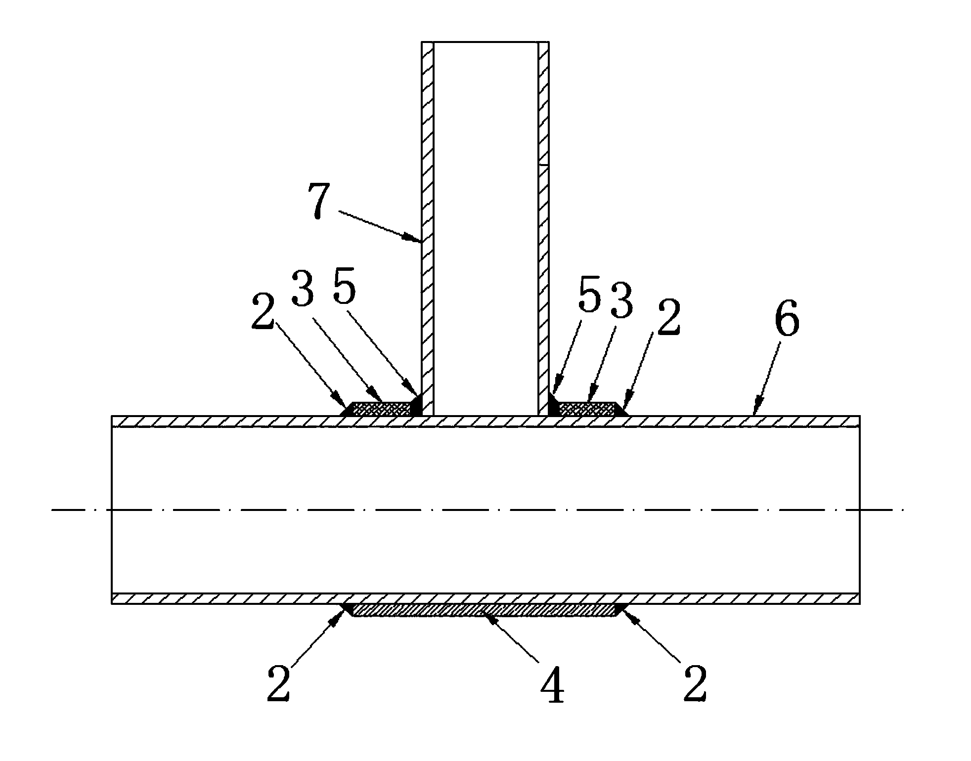
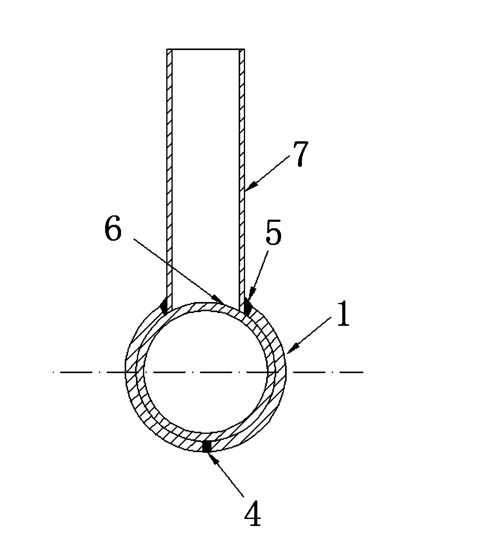
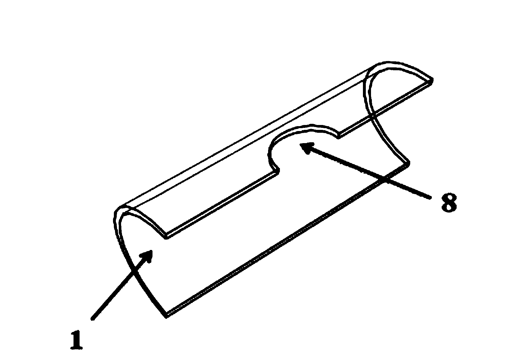
[0026] Such as Figure 1 to Figure 3 As shown in the figure, a ring sleeve used to reinforce intersecting joints of steel pipe trusses includes two semicircular ring sleeves 1, and the middle part of a straight edge of each ring sleeve 1 is provided with a The orifice 8 where the reinforced node main pipe 6 and the reinforced node branch pipe 7 intersect coincides with each other, and the two orifices 8 are butted to form a round hole; the reinforced node branch pipe 7 is welded on the reinforced node main pipe 6, and forms T-shaped pipe node; the two annular sleeves 1 are respectively clamped on the main pipe 6 of the reinforced node, and the orifices 8 of the two annular sleeves 1 are respectively clamped on the branch pipe 7 of the reinforced node; Two annular sleeves 1 are butted together to form an upper surface butt weld 3 and a lower surface butt weld...


PUM


Abstract

The invention discloses a method for reinforcing a steel tube truss tubular joint through ring opening sleeves. The two semicircular sleeves are adopted in the method, an orifice matched with the position where a reinforced joint main tube intersects with a reinforced joint branch tube is formed in the middle of a straight-line side of each sleeve, and the two orifices are in butt joint to form a round hole; the reinforced joint branch tube is welded to the reinforced joint main tube, and a T-shaped tubular joint is formed; the two sleeves are respectively and oppositely clamped onto the reinforced joint main tube, and the two orifices are oppositely clamped onto the reinforced joint branch tube; the two sleeves are in butt joint to form a welding seam, the upper surface of the welding seam and the lower surface of the welding seam are in butt joint, the two orifices and the surface of the reinforced joint branch tube are welded to form a surrounding welding seam, and the two sleeves are connected to the reinforced joint main tube in a sleeved mode to form two lateral welding seams. According to the method, the static performance of the tubular joint can be improved effectively, the anti-seismic and anti-fatigue performance of the joint can be improved effectively, and therefore it is guaranteed that a tube truss structure has higher bearing capacity, better anti-seismic performance and longer service life.

Description

technical field [0001] The invention relates to a method for reinforcing intersecting joints of steel pipe trusses with ring-mouth sleeves, in particular to a method suitable for joint reinforcement and repair of welded pipe truss structures during the service period, and reinforced joints for planned construction of pipe truss structures The processing belongs to the technical field of construction engineering. Background technique [0002] At present, welded intersecting tubular joints have been widely used in large-scale structural projects such as offshore platform structures, bridge structures, and stadiums due to their beautiful shape and superior performance. For typical truss intersecting joints, the branch pipes generally bear the effects of axial force, bending moment and combined force, so the main pipe at the intersection of the truss joints bears the radial load, bending moment load and combined load from the branch pipes. The radial stiffness of the main pipe ...

Claims


Application Information

Patent Timeline
Patent Type & Authority Applications(China)
IPC IPC(8): E04G23/02
Inventor 宋生志魏建军袁宏志
Owner 湖北杰昆建设工程有限责任公司
Why Eureka
Try Eureka