Unhooked anti-touch locking mechanism

A touch lock and locking technology, which is applied in building locks, building construction, construction, etc., can solve the problems that the sliding mechanism and the touch mechanism are not integrated, there is no device to prevent unhooked, unhooked, etc.

Active Publication Date: 2015-08-19
SHAANXI CHINA AERO IND GAS SPRING
View PDF6 Cites 0 Cited by
  • Summary
  • Abstract
  • Description
  • Claims
  • Application Information

AI Technical Summary

Problems solved by technology

One of the currently commonly used slide-in locking mechanisms is that the slide-in mechanism and the touch mechanism are connected by a rigid rod or a steel rope. In this structure, the slide-in mechanism and the touch mechanism are not integrated, and the linkage between the rigid connecting rod or the steel rope Affects the motion of the slide-in mechanism
One is that the sliding mechanism is integrated with the touch mechanism. This structure relies on the linkage between the trigger hook and the locking roller hook on the locking lever to realize unlocking and locking. In actual operation, the trigger hook and the locking roller on the locking lever There will often be a situation where the hook is not hooked, resulting in failure to unlock or lock, causing a lot of inconvenience to the user when closing the locking mechanism
Therefore, the slide-in touch locks of the above two methods do not prevent the hook device from being unlocked, resulting in low performance of this type of slide-in touch lock, which causes a lot of inconvenience to the user when closing the locking mechanism.

Method used


Image

  • Unhooked anti-touch locking mechanism
  • Unhooked anti-touch locking mechanism
  • Unhooked anti-touch locking mechanism

Examples


Embodiment Construction

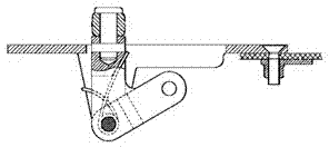
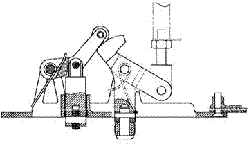
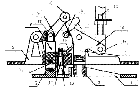
[0014] see image 3 and Figure 4 , an anti-unhook type touch locking mechanism, including a trigger seat 1 and a lock trigger box body 2 that slide and cooperate with each other, the trigger seat 1 is provided with a slope 5 along the door closing direction, and the lock trigger box body 2 includes a trigger hook The roller 3, the trigger roller 4, the trigger lever 6 slidingly connected with the trigger roller 4, the locking lever 7 and the locking roller 8, the trigger lever 6 is connected with the locking lever 7, and the locking roller 8 is arranged on the locking lever 7; the locking trigger box body 2 also includes a trigger hook connecting rod 9 slidingly connected with the trigger hook roller 3, the trigger hook connecting rod 9 is connected with the trigger hook body 10 through a shaft, and one end of the trigger hook body 10 is provided with The locking roller 8 is slidingly connected to the trigger hook 11, and the other end is connected to the pull rod 12 through...


PUM


Abstract

A non-hooked prevention type touching and locking mechanism comprises a triggering base and a locking and triggering box body, wherein the triggering base is in sliding fit with the locking and triggering box body. The triggering base is provided with an oblique plane in the door closing direction, the locking and triggering box body comprises triggering hook idler wheels, a triggering idler wheel, a triggering rod connected with the triggering idler wheel in a sliding mode, a locking rod and a locking idler wheel, a limiting rod is arranged between the triggering rod and a triggering hook connecting rod, the bottom of the limiting rod leans on a compressed spring and is connected with the triggering base, and a raising rod is arranged on the top of the limiting rod; when the triggering hook is in sliding fit with the locking idler wheel, the raising rod is in sliding fit with a triggering hook butting mechanism. According to the mechanism, the limiting rod is added, the situation that two critical states including hooking and disengagement of the locking idler wheel and the triggering hook and sliding into and disengagement of the triggering hook idler wheels and the triggering base exist is avoided, the situation that the locking idler wheel on the triggering hook and the locking rod is not hooked is avoided, performance of the touching and locking mechanism is improved, and locking is firmer and more reliable.

Description

technical field [0001] The invention relates to a door lock mechanism, in particular to an unhooked anti-touch locking mechanism. Background technique [0002] The slide-in locking mechanism is one of the ways to meet the heavy load mechanical lock. One of the currently commonly used slide-in locking mechanisms is that the slide-in mechanism and the touch mechanism are connected by a rigid rod or a steel rope. In this structure, the slide-in mechanism and the touch mechanism are not integrated, and the linkage between the rigid connecting rod or the steel rope Affects the motion of the slide-in mechanism. One is that the sliding mechanism is integrated with the touch mechanism. This structure relies on the linkage between the trigger hook and the locking roller hook on the locking lever to realize unlocking and locking. In actual operation, the trigger hook and the locking roller on the locking lever The situation of not hooking often occurs, causing unblanking or locking ...

Claims


Application Information

Patent Timeline
Patent Type & Authority Patents(China)
IPC IPC(8): E05B63/24
Inventor 张晓冬
Owner SHAANXI CHINA AERO IND GAS SPRING
Why Eureka
Try Eureka