Vane structure for weakening axial flow pump vane top leakage flow and leakage vortex

A technology of blade tip leakage and blade structure, which is applied to the components, pumps, and pump elements of pumping devices for elastic fluids, can solve problems such as increased workload, complex blade shapes, and difficult processing, and achieves improved lift and Effects of hydraulic efficiency, improved hydraulic stability, and mature processing methods

Inactive Publication Date: 2014-03-26
JIANGSU UNIV
View PDF7 Cites 16 Cited by
  • Summary
  • Abstract
  • Description
  • Claims
  • Application Information

AI Technical Summary

Problems solved by technology

However, the shape of this kind of blade is more complex, difficult to process, increases the workload, and may not meet the original design of the impeller; the patent "a high-efficiency axial flow pump impeller (patent number: ZL200920043160.9)" has been authorized. The airfoil shape of different circumferential sections of the blade is used to obtain better hydraulic performance, but the traditional structure is still used in the tip area of ​​the impeller blade
It can be seen that the improvement of the blades of axial flow pumps is mostly the overall change of the shape of the blades, and a blade structure that improves the shape of the blade tip to weaken the leakage flow and leakage vortex of the blade tip has not yet been proposed.

Method used


Image

  • Vane structure for weakening axial flow pump vane top leakage flow and leakage vortex
  • Vane structure for weakening axial flow pump vane top leakage flow and leakage vortex
  • Vane structure for weakening axial flow pump vane top leakage flow and leakage vortex

Examples


Embodiment Construction

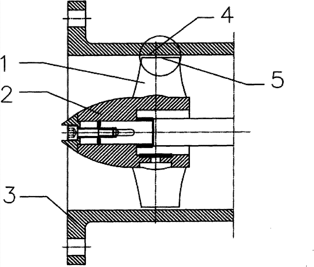
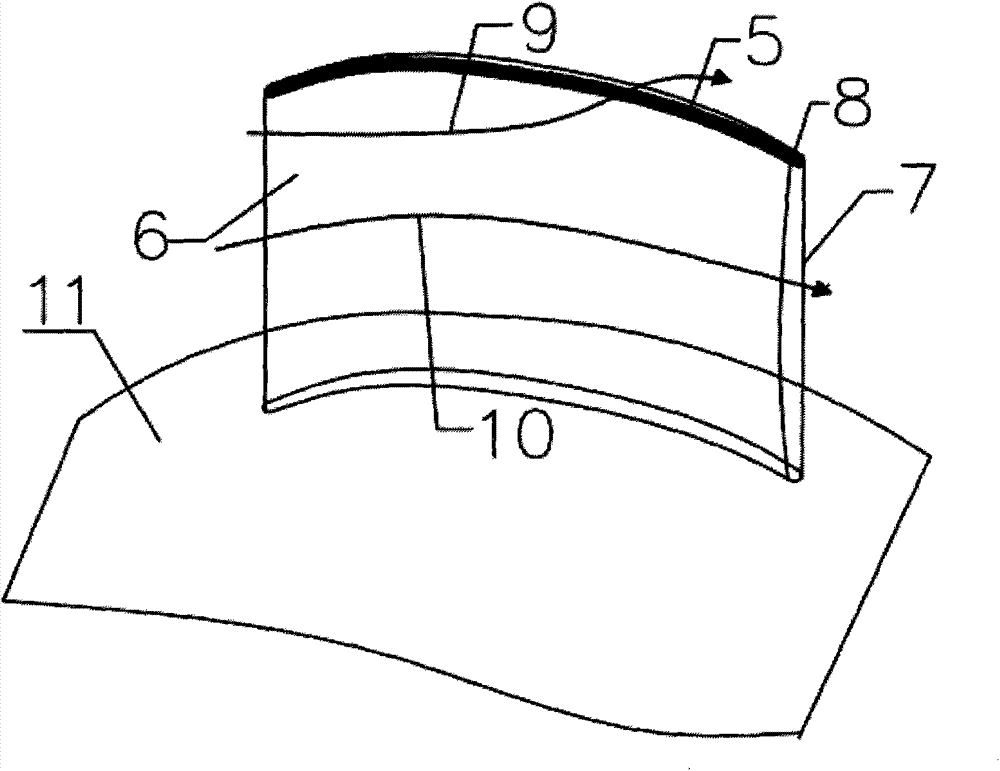
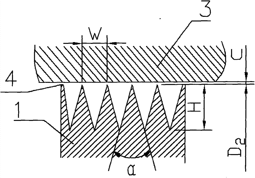
[0014] A partial schematic of an axial flow pump figure 1 , including the impeller blade (1) of the axial flow pump, the impeller hub (2), the runner chamber (3), the impeller gap (4) and the blade top (5). The zigzag labyrinth structure of the present invention is designed on the blade top (5), and the distance between the impeller blade (1) and the wall surface of the runner chamber (3) is the impeller gap (4). The impeller blades are fixed on the impeller hub (2) by a fixing piece. Due to the pressure difference between the blade pressure surface (7) and the suction surface (6), the liquid (10) between the vane passages of the axial flow pump leaks from the blade pressure surface (7) to the The suction surface (6) passes through the zigzag labyrinth structure (8) of the blade top, which increases the fluid flow resistance and consumes part of the kinetic energy of the fluid flowing through the blade tip gap, thereby reducing the leakage of the blade tip gap and inhibiting ...


PUM


Abstract

The invention relates to a vane structure for weakening axial flow pump vane top leakage flow and leakage vortex. The vane structure is characterized in that an axial flow pump vane top is machined to be of a mazy structure which is in a sawtooth shape and has a certain gap, height, width, tooth numbers, tooth top angles and the like. The vane structure has the advantages that proper sawtooth size is selected, through the vane tip mazy structure of an axial flow pump, energy loss is increased when fluid passes through the vane top gap, leakage amount is lowered, accordingly, vane top leakage flow and leakage vortex are weakened, and the hydraulic efficiency and the operation stability of the axial flow pump are improved.

Description

Technical field [0001] The invention relates to a vane structure for weakening leakage flow and leakage vortex at the vane top of an axial flow pump. The vane top is designed as a zigzag labyrinth structure, belonging to the technical field of fluid machinery products. Background technique [0002] Axial flow pumps have been widely used in farmland irrigation and drainage, flood control and drainage, urban water supply and drainage, and cross-basin water transfer projects due to their large flow, low head, simple structure, and convenient use. Running stability has important practical significance. In the axial flow pump impeller, due to the structural characteristics of the axial flow impeller, there is inevitably a gap between the top of the impeller blade and the runner chamber. The flow of nearly 20% of the area of ​​the blade runner is affected. Under the action of the pressure between the working surface and the suction surface of the blade of the axial flow pump, a ...

Claims


Application Information

Patent Timeline
Patent Type & Authority Applications(China)
IPC IPC(8): F04D29/38
Inventor 张德胜邵佩佩施卫东王海宇潘大志胡啟祥
Owner JIANGSU UNIV
Why Eureka
Try Eureka