An oil circuit structure of a hydraulic retarder and its method for reducing no-load loss

A technology of hydraulic retarder and no-load loss, which is applied in the direction of liquid resistance brakes, brake components, brake types, etc., can solve the problem of high residual torque of hydraulic retarder, improve overall performance, reduce weight, improve The effect of using performance

Active Publication Date: 2017-05-03
深圳市特尔佳汽车科技有限公司
View PDF9 Cites 0 Cited by
  • Summary
  • Abstract
  • Description
  • Claims
  • Application Information

AI Technical Summary

Problems solved by technology

[0005] One of the objectives of the present invention is to provide an oil circuit structure of a hydraulic retarder, which solves the problem of high residual torque when the hydraulic retarder is not working, and reduces its no-load loss and lowers the cost of using the vehicle

Method used


Image

  • An oil circuit structure of a hydraulic retarder and its method for reducing no-load loss
  • An oil circuit structure of a hydraulic retarder and its method for reducing no-load loss
  • An oil circuit structure of a hydraulic retarder and its method for reducing no-load loss

Examples


Embodiment 1

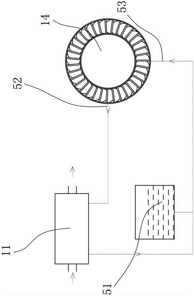
[0039] Example 1: figure 2 , Figure 4 with Figure 7 to Figure 12 The first embodiment of the present invention is shown. The oil circuit structure of the hydraulic retarder of the present invention includes an oil circuit structure formed by the working chamber 14, the heat exchanger 11 and the oil tank 51 in sequence. A bypass valve 2 is provided on the oil path between the bypass port 13 of the cavity 14 and the heat exchanger 11.

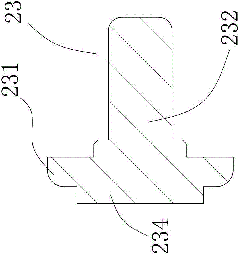
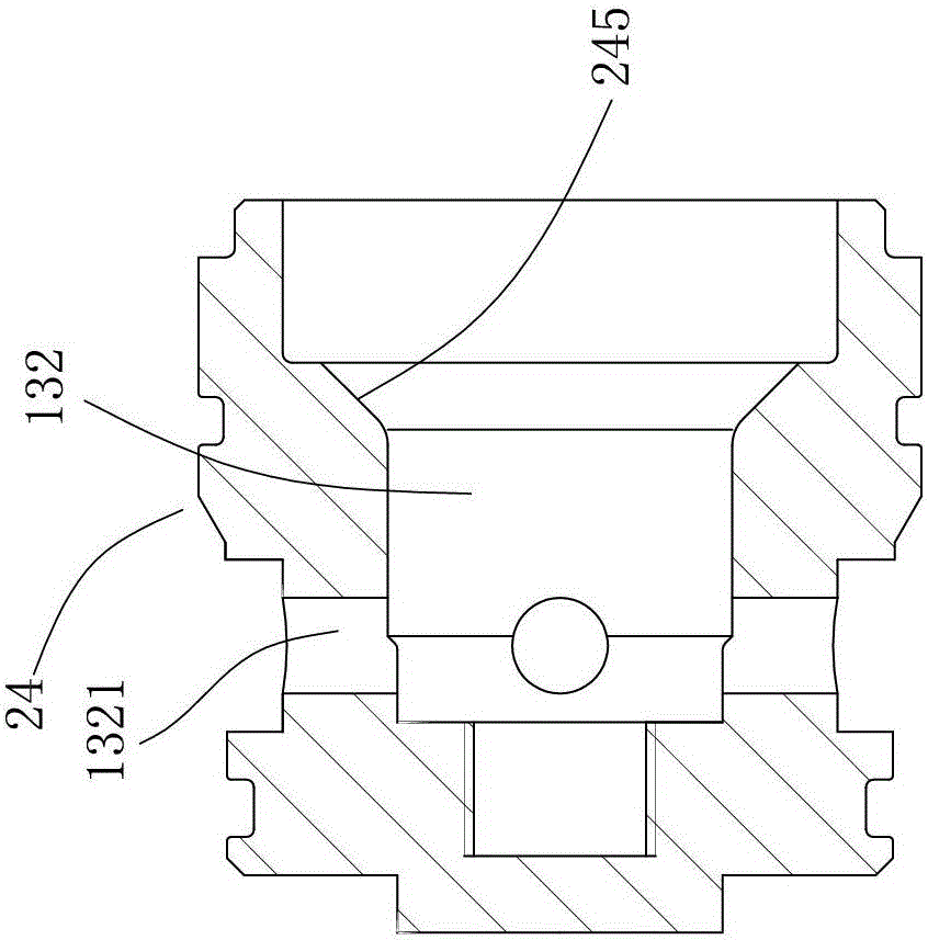
[0040] The bypass valve 2 includes a valve seat 24 and a valve cover 22 that are engaged with each other. A valve core 23 is provided in the valve cavity 132 of the valve seat 24, and a bypass valve oil outlet 1321 is provided at one end of the valve cavity 132. The other end of the valve cavity 132 is provided with a sealing surface, the sealing end 231 of the valve core 23 corresponds to the sealing surface, and a spring 6 is provided between at least one end of the valve cavity 132 and the sealing end 231 of the valve core 23. In this embodimen...

Embodiment 2

[0055] Example 2: figure 2 with Figure 5 The second embodiment of the present invention is shown. The oil path structure of a hydraulic retarder of the present invention includes an oil path structure formed by the working chamber 14, the heat exchanger 11 and the oil tank 51 in sequence. A bypass valve 2 is provided on the oil path between the bypass port 13 of the cavity 14 and the heat exchanger 11.

[0056] The bypass valve 2 includes a valve seat 24 and a valve cover 22 that are engaged with each other. A valve core 23 is provided in the valve cavity 132 of the valve seat 24, and a bypass valve oil outlet 1321 is provided at one end of the valve cavity 132. The other end of the valve cavity 132 is provided with a sealing surface, the sealing end 231 of the valve core 23 corresponds to the sealing surface, and a spring 6 is provided between at least one end of the valve cavity 132 and the sealing end 231 of the valve core 23. In this embodiment In an example, the spring 6 i...

Embodiment 3

[0071] Example 3: image 3 , Image 6 with Figure 7 to Figure 11 The third embodiment of the present invention is shown. The oil circuit structure of a hydraulic retarder of the present invention includes an oil circuit structure formed by the working chamber 14, the heat exchanger 11 and the oil tank 51 in sequence. A bypass valve 2 is provided on the oil path between the bypass port 13 of the cavity 14 and the heat exchanger 11. The oil outlet of the bypass valve 2 is in communication with the oil inlet 53 of the working chamber 14.

[0072] The bypass valve 2 includes a valve seat 24 and a valve cover 22 that are engaged with each other. A valve core 23 is provided in the valve cavity 132 of the valve seat 24, and a bypass valve oil outlet 1321 is provided at one end of the valve cavity 132. The other end of the valve cavity 132 is provided with a sealing surface, the sealing end 231 of the valve core 23 corresponds to the sealing surface, and a spring 6 is provided between ...


PUM


Abstract

The invention discloses an oil circuit structure of a hydrodynamic retarder. The oil circuit structure is formed by a working cavity, a heat exchanger and an oil tank in a sequential communication mode. A bypass valve is arranged on an oil circuit between a bypass port of the working cavity and the heat exchanger. The invention further discloses a method for lowering no-load loss. When the hydrodynamic retarder is in a no-load state, air exists in the working cavity, the bypass valve is opened all the time, the air in the working cavity is driven by a rotor impeller to pass through the bypass valve and an oil inlet of the working cavity to flow back to the working cavity, and a small air flow cycle is formed. As a result, the effect of lowering remnant torque is achieved, the no-load loss of the hydrodynamic retarder is lowered, using cost is lowered, and the using performance of the hydrodynamic retarder is improved at the same time. When the hydrodynamic retarder works, the bypass valve is closed, and therefore the torque of the hydrodynamic retarder is greatly increased.

Description

Technical field [0001] The invention relates to a hydraulic retarder, in particular to an oil circuit structure of the hydraulic retarder and a method for reducing no-load loss. Background technique [0002] The hydraulic retarder is an auxiliary braking device for motor vehicles. It is mainly composed of a stator impeller, a rotor impeller, a retarder shell, a working chamber, a heat exchanger and an oil tank. Its essence is a rotary damping device , The rotor impeller is used to drive the working fluid to impact with the stator impeller to generate reverse scroll torque, which converts the kinetic energy of the vehicle into the thermal energy of the working fluid, thereby slowing the vehicle. Driven by the rotor impeller, the working fluid in the working cavity enters the heat exchanger through the retarder oil outlet to exchange oil and water, and then flows back to the working cavity from the oil inlet, so that the heat energy of the working fluid is cooled by the engine cool...

Claims


Application Information

Patent Timeline
Patent Type & Authority Patents(China)
IPC IPC(8): F16D57/02F16D65/00
Inventor 闻维维文光安施国飞
Owner 深圳市特尔佳汽车科技有限公司
Why Eureka
Try Eureka