Engine balancer

A technology of balancing device and engine, applied in the direction of transmission, gear transmission, hoisting device, etc., can solve the problems of reduced gear assembly accuracy, difficulty in maintaining backlash accuracy, and difficulty in application.

Inactive Publication Date: 2014-03-26
HITACHI AUTOMOTIVE SYST LTD
View PDF9 Cites 2 Cited by
  • Summary
  • Abstract
  • Description
  • Claims
  • Application Information

AI Technical Summary

Problems solved by technology

However, when the installation position of the balancer is changed from the conventional one in accordance with the diversification of the engine system in recent years, the assembly accuracy of the gears will be lowered due to the influence of thermal deformation, overlapping of machining dimensional deviations, etc. As a result, Sometimes it becomes difficult to maintain the accuracy of the backlash
Moreover, the application of scissor gears with complex and expensive structures becomes difficult due to strict cost requirements for the product

Method used


Image

  • Engine balancer
  • Engine balancer
  • Engine balancer

Examples


Embodiment 1

[0029] In this embodiment, a description will be given of a device structure that includes a transmission gear for transmitting power in addition to a gear for synchronizing counterweights.

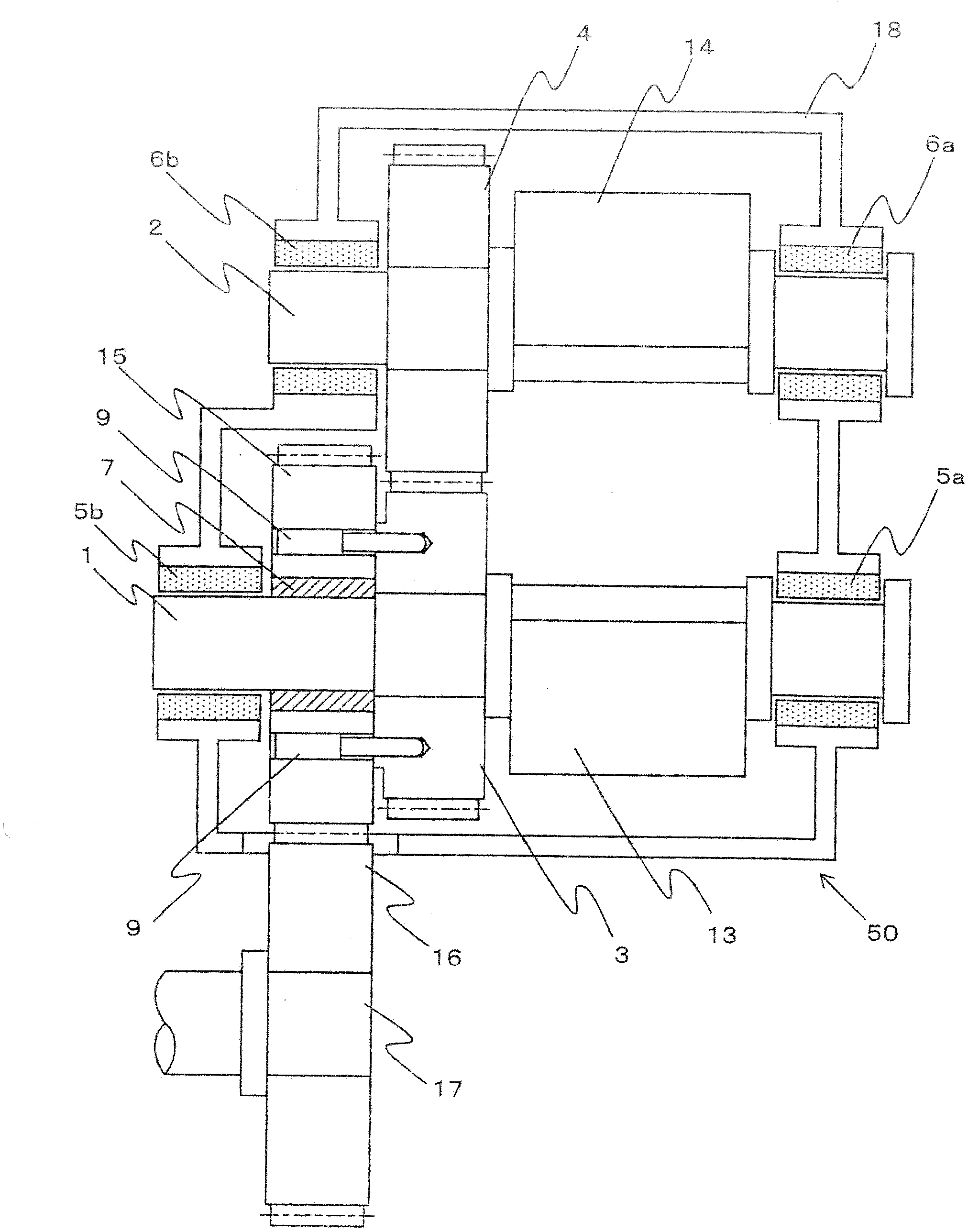
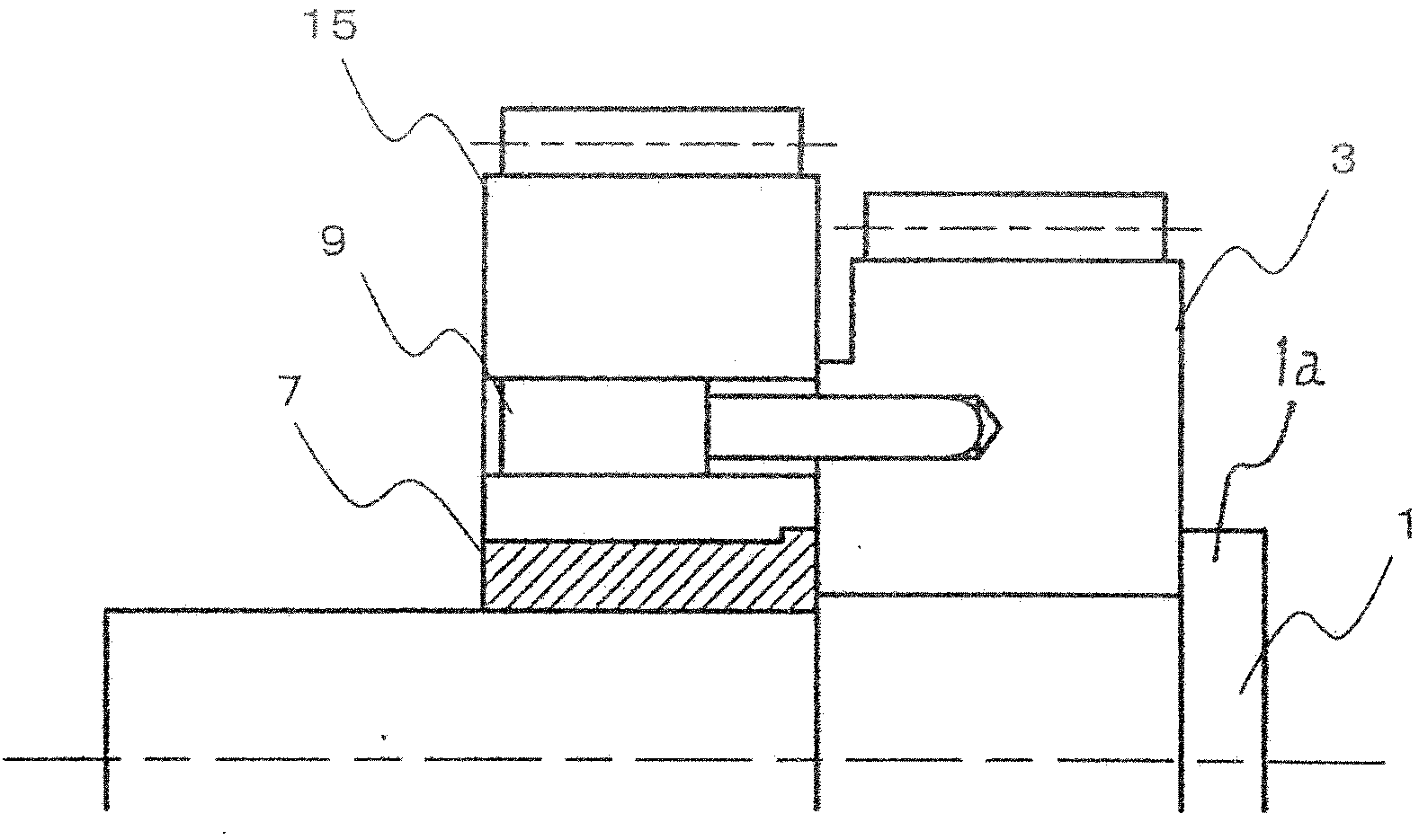
[0030] figure 1 It is an example of the structural diagram of the balancing device of this embodiment. The balancer 50 is mounted on the bottom of an unshown engine block, and transmits power derived from a not-shown crankshaft to the input gear 16 provided coaxially with the input shaft 17 . On the other hand, in the balancing device 50, the driving shaft 1 is fitted with the driving gear 3 and is rotatably supported by the driving gear bearings 5a, 5b, and the driven shaft 2 is fitted with the driven gear 4 and is rotatably supported by the driven gear bearing 6a. , 6b is rotatably supported, and the driving shaft counterweight 13 and the driven shaft counterweight 14 are arranged at positions deviated from the rotation center on each shaft, and the driving gear 3 and the driven gear 4...

Embodiment 2

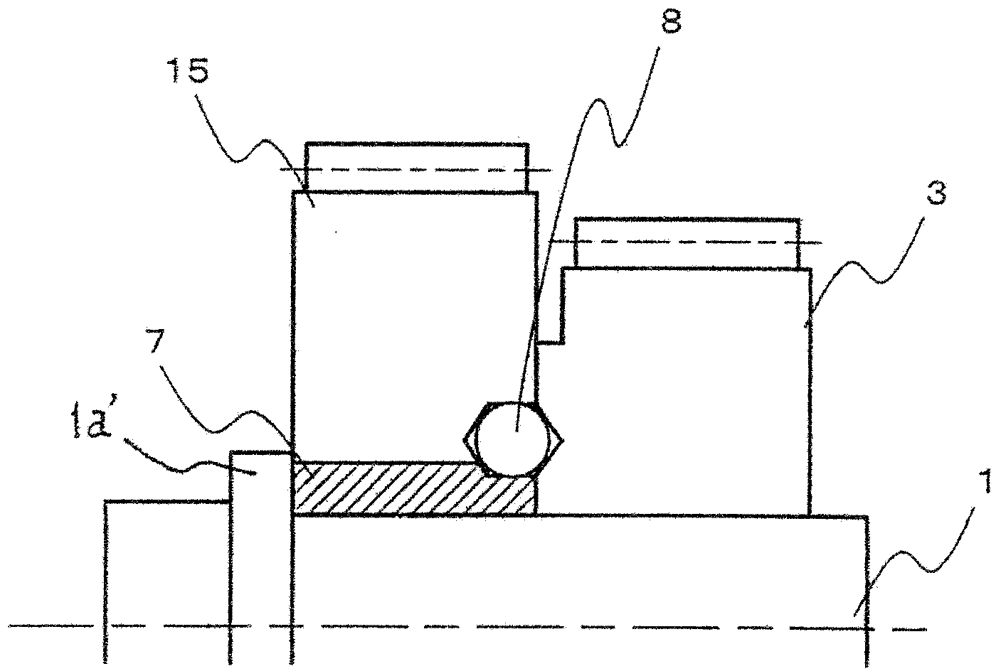
[0037] Figure 5 This is an example of a block diagram of the engine balancer when the transmission gear of the present embodiment is omitted. The input gear 16 is directly meshed with the drive gear 3, the drive shaft 1 and the sleeve 7, and the sleeve 7 and the drive gear 3 are pressed in, and the fixed pin 9 is firmly pressed into the flange 12 integrally formed on the drive shaft 1, and The aperture that is provided with on the driving gear 3, prevents the separation of the two. Since other structures and functions are the same as those in Embodiment 1, descriptions thereof are omitted. By adopting such a structure, one gear can be omitted, and not only an inexpensive system can be configured, but also the size of the body can be reduced.


PUM


Abstract

The invention provides an engine balancer. It is therefore an object of the present invention to provide a highly reliable gear device wherein in an apparatus in which the vibrational torque transmitted by gears is higher in amplitude than the static torque, when the backlash is allowed to be relatively large, the tooth-hit shock at collision of the tooth surface is buffered and the precision of the coaxial state between the gear and the gear shaft is retained to reduce the whine noise and the rattle noise of the gear, and the tooth surface damage due to the one-sided contact and the like is prevented and the removal of the gear due to the fluctuating load in the axial direction is also prevented. Specifically, there is provided a gear pair including a driving gear 3, a driving shaft 1, and a driven gear 4, the gear pair being formed by interlocking the driving gear 3 with the driven gear 4, wherein the driving gear 3 is engaged with the driven gear 4, the gear pair further including a fixing member to elastically fix the driving gear 3 onto the driving shaft 1.

Description

technical field [0001] The present invention relates to a vibration reduction mechanism for reducing vibration and noise of an engine balancer, and more particularly to a gear fixing method for reducing vibration of an engine balancer composed of parallel shaft gear elements such as helical gears. Background technique [0002] Most of the prime movers installed in passenger cars are reciprocating engines, and in engines with a small number of cylinders and high explosive power, such as four-cylinder diesel engines, engine vibration occurs in its explosive cycle, which brings serious shock to the occupants. Therefore, the bottom of the engine is sometimes equipped with a vibration reduction device called a balancer. [0003] In this device, a counterweight is provided at an eccentric position on a rotating shaft, and vibration is canceled out by utilizing an inertial force generated by rotating the shaft. For example, in a four-stroke four-cylinder engine, the output shaft (...

Claims


Application Information

Patent Timeline
Patent Type & Authority Applications(China)
IPC IPC(8): F16F15/26F16H55/14
CPCF16D3/14F16F15/265F16H1/20F16H57/0006F16H2057/0012F16D1/0858F16C3/20
Inventor 大野耕作平野崇东藤保
Owner HITACHI AUTOMOTIVE SYST LTD
Why Eureka
Try Eureka