
Electro-hydraulic actuator

An electro-hydraulic actuator and controller technology, applied in the field of actuators, can solve the problems of poor cylinder positioning accuracy, poor cylinder positioning effect, increased internal leakage, etc., and achieve the effect of ensuring positioning accuracy and stability

Active Publication Date: 2014-03-26
CHONGQING CHUANYI AUTOMATION
View PDF7 Cites 24 Cited by
  • Summary
  • Abstract
  • Description
  • Claims
  • Application Information

AI Technical Summary

Problems solved by technology

[0003] Existing electro-hydraulic actuators use a single servo motor and an oil pump to jointly drive the cylinder. However, the response speed and positioning accuracy of this cylinder speed control system have always been contradictory. When the response speed of the cylinder is fast, the The positioning accuracy of the last stage is poor, and when the positioning accuracy of the oil cylinder is required to be high, the response speed of the oil cylinder needs to be slowed down, and when the oil pump is running at a low speed, the internal leakage increases, and the volume ratio and displacement become unstable, resulting in The actual cylinder positioning effect is poor
[0004] In addition, the electro-hydraulic actuator usually includes an accumulator to provide hydraulic oil for the oil pump. However, after the accumulator is used for a period of time, the pressure oil in the accumulator decreases, and the energy can only be stored manually, which affects the performance of the electro-hydraulic actuator. Normal work; and after the accumulator fails, the staff cannot find it in time, which has a negative impact on the normal operation of the electro-hydraulic actuator
[0005] In summary, how to solve the problem of poor positioning accuracy of the cylinder of the electro-hydraulic actuator has become an urgent problem to be solved by those skilled in the art

Method used


Image

  • Electro-hydraulic actuator
  • Electro-hydraulic actuator

Examples


Embodiment Construction

[0032] The core of the invention is to provide an electro-hydraulic actuator, which improves the positioning accuracy of the oil cylinder.

[0033] The following will clearly and completely describe the technical solutions in the embodiments of the present invention with reference to the accompanying drawings in the embodiments of the present invention. Obviously, the described embodiments are only part of the embodiments of the present invention, not all of them. Based on the embodiments of the present invention, all other embodiments obtained by persons of ordinary skill in the art without making creative efforts fall within the protection scope of the present invention.

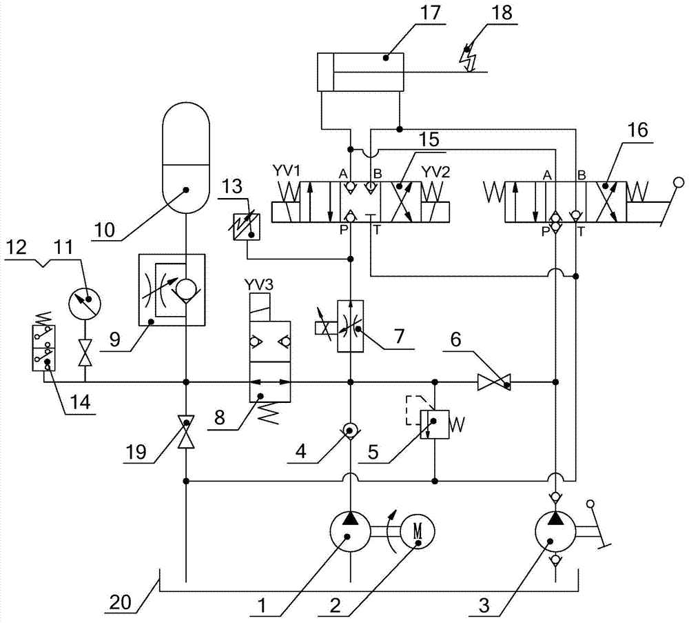
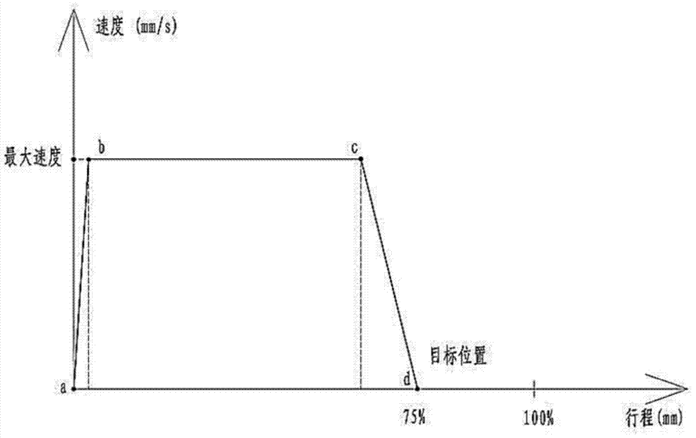
[0034] Please refer to figure 1 , figure 1 A schematic diagram of an electro-hydraulic actuator provided by an embodiment of the present invention; figure 2 A cylinder speed-displacement positioning control diagram of an electro-hydraulic actuator provided by an embodiment of the present invention.

[...


PUM


Abstract

The invention discloses an electro-hydraulic actuator. The electro-hydraulic actuator comprises a servo motor, an oil pump, a three-position four-way electromagnetic directional valve, an oil cylinder, a displacement sensor, a controller and a proportional velocity regulating valve. The inlet of the proportional velocity regulating valve is communicated with the oil pump, the outlet of the proportional velocity regulating valve is communicated with a port P of the three-position four-way electromagnetic directional valve, and the proportional velocity regulating valve is electrically connected with the controller. When the electro-hydraulic actuator works, the servo motor, the oil pump and the proportional velocity regulating valve jointly act, hydraulic oil is conveyed into the oil cylinder, due to the fact that the proportional velocity regulating valve can stably control the output flow of a system in an infinitely small mode, the oil cylinder can be made to stably operate at very low speed, the defect that the oil pump can not stably output hydraulic oil in the low-speed operation process caused by factors of the oil pump itself is overcome, and locating accuracy of the oil cylinder is guaranteed.

Description

technical field [0001] The invention relates to the technical field of actuators, in particular to an electro-hydraulic actuator. Background technique [0002] Actuators include electric actuators, pneumatic actuators and electro-hydraulic actuators, which are generally used to drive and control the operation of valves. [0003] Existing electro-hydraulic actuators use a single servo motor and oil pump to jointly drive the cylinder. However, the response speed and positioning accuracy of this cylinder speed control system have always been contradictory. When the response speed of the cylinder is fast, the The positioning accuracy of the last stage is poor, and when the positioning accuracy of the oil cylinder is required to be high, the response speed of the oil cylinder needs to be slowed down, and when the oil pump is running at a low speed, the internal leakage increases, and the volume ratio and displacement become unstable, resulting in The actual cylinder positioning ...

Claims


Application Information

Patent Timeline
IPC IPC(8): F16K31/122F15B1/02F15B11/042
CPCF15B1/02F15B11/042
Inventor 李巧向学院游军
Owner CHONGQING CHUANYI AUTOMATION
Learn More