A building lighting and signage system

A technology for buildings and signs, applied in the field of building lighting and signage systems, can solve problems such as large safety hazards, large amount of engineering, complicated equipment, etc., and achieve the effects of low cost, simple structure and easy installation.

Active Publication Date: 2016-03-02
BEIJING EAST VIEW NEW ENERGY TECH
View PDF6 Cites 0 Cited by
  • Summary
  • Abstract
  • Description
  • Claims
  • Application Information

AI Technical Summary

Problems solved by technology

[0005] The present invention aims at the problems existing in the existing light pipe lighting system or electric lighting system, such as problems such as large potential safety hazards, waste of resources, large amount of work, complicated equipment, etc., and proposes a new type of fluid lighting and marking system, which adopts The light storage properties of long-lasting luminescent materials collect and store sunlight or other light sources and transmit them to areas that require lighting and marking

Method used


Image

  • A building lighting and signage system
  • A building lighting and signage system

Examples


Embodiment approach 1

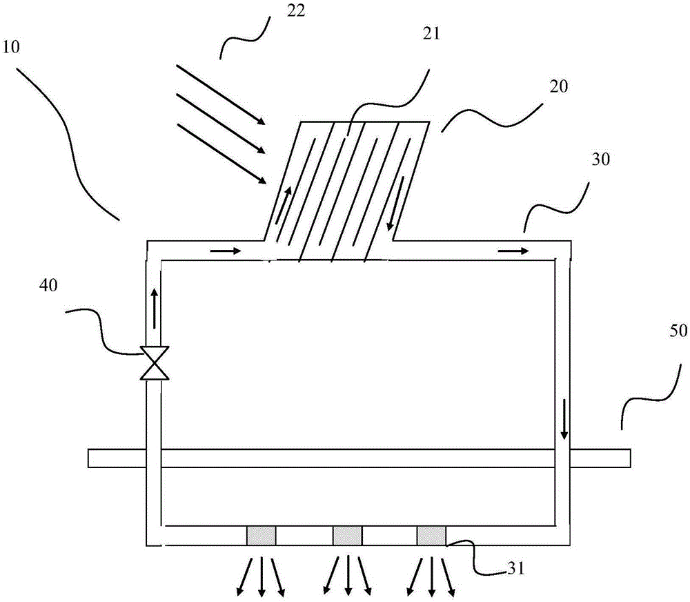
[0023] Such as figure 1 The building lighting and signage system 10 at least includes a light receiving device 20 , a transmission pipe 30 , a circulating power device 40 and a light output device 31 . The transmission pipeline can be arranged on the body of wall or the ground 50 of the building, and the light receiving device 20 is made of transparent material; the closed-loop transmission pipeline 30 connected with the light receiving device 20, the material of the transmission pipeline 30 can be metal material or other Material. The transmission pipe 30 is connected to the room or the area that needs to be illuminated, and is connected with a transparent light output device 31; a power device 40 for driving fluid circulation is also installed on the transmission pipe 30, and the power device 40 is used to provide fluid circulation. The required power; the inside of the pipeline is a fluid material, which can be a transparent fluid material, and the long afterglow luminesce...

Embodiment approach 2

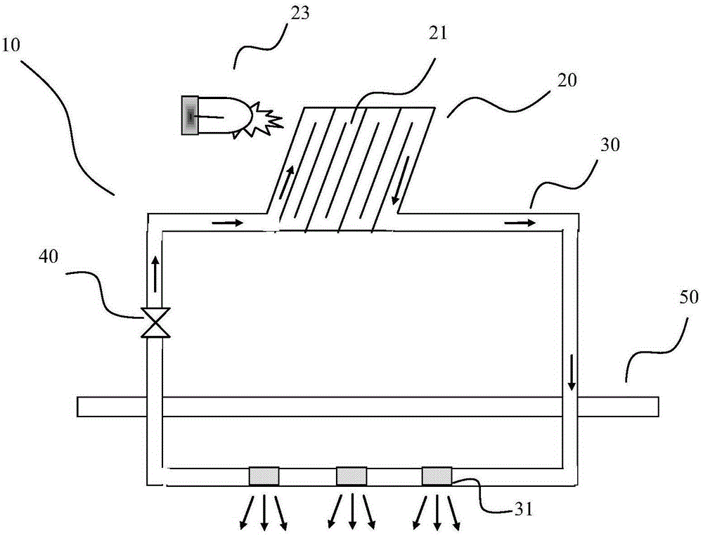
[0029] figure 2 It is a schematic diagram of the second embodiment of the fluid lighting system. The difference between this system and Embodiment 1 is that the radiant energy received by the system comes from an artificial light source 23 , and the devices and functions of other parts are the same as Embodiment 1, and will not be described again here. The purpose of using artificial light sources is to meet the requirements of the system in specific conditions, such as locations that do not receive sunlight easily or other requirements. In this way, the system can turn on the artificial light source and the system when lighting or marking is required, so that the energy can be delivered to the location where lighting or marking is required.

[0030] The lighting system is simple and beautiful, and its installation position and angle can be changed flexibly during installation, and it can meet different lighting requirements, which provides convenience for users with differe...


PUM


Abstract

The invention discloses a building lighting and marking system. The system at least comprises a light receiving device, a light output device, a closed loop delivery pipeline and a circulation power device, wherein the closed loop delivery pipeline and the circulation power device are connected with the light receiving device and the light output device and arranged in the wall of a building or the ground. Fluid material capable of flowing is filled into the delivery pipeline, steady persistence material is evenly dispersed in the fluid material, the fluid material mixed with the steady persistence material flows along the delivery pipeline under the driving of the circulation power device, and light is emitted outside through the light output device arranged on the delivery pipeline. The building lighting and marking system is safe, easy to install and convenient to adjust, and energy is saved.

Description

technical field [0001] The invention relates to a building lighting and identification system. Background technique [0002] At present, the indoor lighting of buildings is generally opened with windows, through which the external sunlight enters the room. For buildings that are relatively closed and cannot be directly illuminated, such as basements, the indoor lighting or other signs generally use electric lighting. . The use of lighting fixtures not only wastes a lot of electric energy, but also has potential safety hazards. Especially for some special spaces, such as processing workshops, shopping malls and other environments, the potential safety hazards are particularly prominent. [0003] In order to introduce sunlight into buildings that cannot be directly illuminated, a tubular skylight lighting system was invented. U.S. Patent 5,502,935, 6,219,977, 6,256,947, 6,363,667, 7,082,726 etc. all disclose a kind of roof skylight device respectively, and its basic structu...

Claims


Application Information

Patent Timeline
Patent Type & Authority Patents(China)
IPC IPC(8): F21S15/00
Inventor 刘志东刘志方徐登辉
Owner BEIJING EAST VIEW NEW ENERGY TECH
Why Eureka
Try Eureka