Current control device of LED module

A light-emitting diode, current control technology, applied in lighting devices, electroluminescent light sources, electric lamp circuit layout, etc., can solve problems such as troublesome control, slow response, inconvenience, etc.

Inactive Publication Date: 2007-11-28
陈建中
View PDF0 Cites 16 Cited by
  • Summary
  • Abstract
  • Description
  • Claims
  • Application Information

AI Technical Summary

Problems solved by technology

[0007] Therefore, this design is not only cumbersome and inconvenient to control when the current is small, but also because most of the current is absorbed by the Zener diode D z Absorption is relatively slow in response to control, and it is not an ideal current-limiting circuit. Therefore, there is still room for improvement and gain in the control and current-limiting protection of the entire LED module.

Method used


Image

  • Current control device of LED module
  • Current control device of LED module
  • Current control device of LED module

Examples


Embodiment Construction

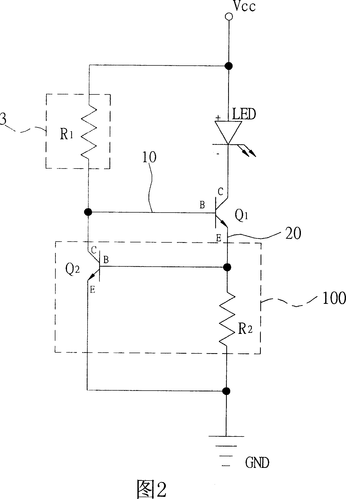
[0046] Please refer to FIG. 2, which is a schematic diagram of the circuit structure of the first embodiment of the current control device of the light-emitting diode module of the present invention. As shown in the figure, the present invention provides a current control device of the light-emitting diode module, which includes: current limiting protection Circuit 100, current control circuit 3 and first transistor Q 1 . Wherein, the current limiting protection circuit 100 at least includes a second transistor Q 2 And the second resistor R 2 , And the first transistor Q 1 With the second transistor Q 2 Use NPN transistors to describe.

[0047] In addition, the current control circuit 3 includes a first resistor R 1 , And the first resistor R 1 Can be a variable resistor, by manually adjusting the first resistor R 1 The first current signal 10 generated by the resistance value is used to adjust the luminous power of the light-emitting diode LED, wherein at least one light-emitting...


PUM


Abstract

This invention relates to a current control device of a simplified LED module including: a current control circuit, a first transistor and a current limiting protection circuit, in which, the current control circuit includes a first resistor generating a first current signal to regulate the radiation power of at least one LED, the first transistor controls the operation of the LED with the help of the first current signal and generates a second current signal, and a second transistor in the current-limiting protection circuit can decide open or close of channels based on the second current signal and the second resistor to further control said first current signal, in this way, the module can control the radiation power by the current control circuit and protect it with the help of current limit of the protection circuit.

Description

Technical field [0001] The invention relates to a control device of a light emitting diode module, in particular to a current control device of a light emitting diode module. Background technique [0002] In recent years, due to the rapid development of a variety of mobile communication products and multimedia products, the demand for various types of liquid crystal displays has increased day by day, and the backlight module in the liquid crystal display has gradually replaced the original cold cathode lamp (CCFL) by light emitting diodes (LED) , So it also drives the development of light-emitting diodes. In addition, compared with traditional incandescent light bulbs, High-power Light Emitting Diodes (HP LEDs) also have the advantages of power saving, long service life, high durability and fast response speed, so that they can emit light. The potential of diodes in the general lighting market cannot be ignored. From households, public constructions to automobiles, based on their...

Claims


Application Information

Patent Timeline
Patent Type & Authority Applications(China)
IPC IPC(8): H05B33/08H05B37/02H05B44/00
CPCY02B20/341Y02B20/30
Inventor 陈建中
Owner 陈建中
Why Eureka
Try Eureka