Impact reducing tail-section linear explosion separating device for small-diameter assisted takeoff rocket

An explosive separation and small-diameter technology, which is applied in the direction of projectiles, self-propelled bombs, and offensive equipment, can solve problems such as difficulty in meeting batch production requirements, affecting the normal operation of surrounding equipment, difficulty in installation, operation, and inspection, and achieves improved separation The effect of safety, small structure size and low separation impact

Active Publication Date: 2014-03-26
BEIJING INST OF ASTRONAUTICAL SYST ENG +1
View PDF6 Cites 16 Cited by
  • Summary
  • Abstract
  • Description
  • Claims
  • Application Information

AI Technical Summary

Problems solved by technology

[0003] The existing linear explosive separation device is mainly used for the separation of two sections of a large-diameter rocket, and has the following disadvantages: the linear explosive separation device of a large-diameter rocket adopts front-end positioning, and if the protective cover of a small-diameter rocket is positioned by the front end, Its installation, operation and inspection are difficult; the existing linear explosive separation device is applied to small-diameter rockets, and the impact of the separation explosion is too large, which affects the normal operation of

Method used


Image

  • Impact reducing tail-section linear explosion separating device for small-diameter assisted takeoff rocket
  • Impact reducing tail-section linear explosion separating device for small-diameter assisted takeoff rocket
  • Impact reducing tail-section linear explosion separating device for small-diameter assisted takeoff rocket

Examples


Embodiment Construction

[0035] The present invention will be further described in detail below in conjunction with the accompanying drawings and specific embodiments.

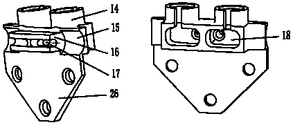
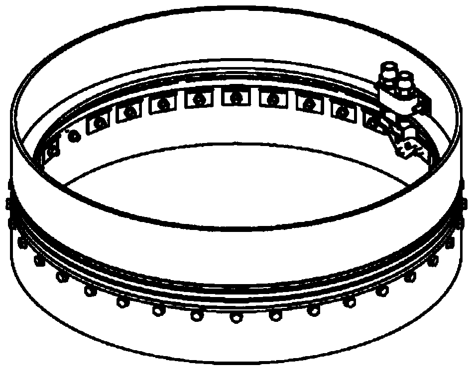
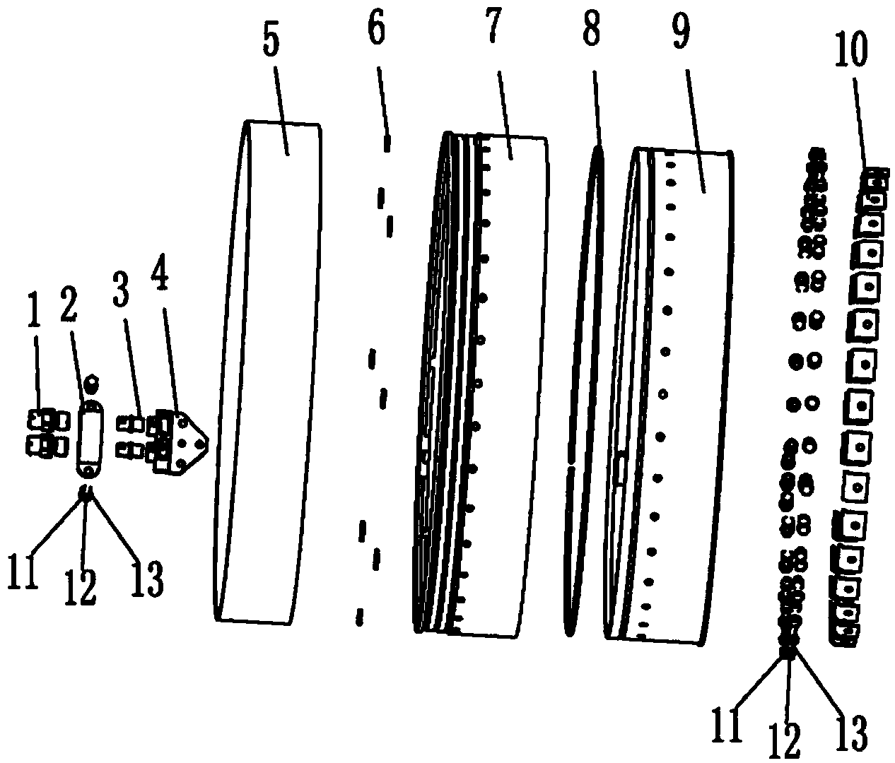
[0036] Such as figure 1 Shown is the schematic diagram of the structure of the linear explosive separation device of the present invention, figure 2 Shown is an exploded view of the structure of the linear explosive separation device of the present invention, image 3 It is a cross-sectional structure diagram of the detonation position of the linear explosive separation device of the present invention, Figure 4 It is a cross-sectional structure diagram of the non-initiation position of the linear explosive separation device of the present invention. It can be seen from the figure that the explosive separation device of the present invention includes a detonator 1, a split detonation joint, a shock-reducing shell, an explosive cable 8, a glass protective cover 9, and an energy-absorbing pad 10. Bolts 11, flat washers 12 and nuts 13, ...


PUM


Abstract

The invention relates to an impact reducing tail-section linear explosion separating device for a small-diameter assisted takeoff rocket. The impact reducing tail-section linear explosion separating device comprises a detonator, a split type detonating connector, an impact reducing shell, an explosive fuse, a glass protective cover and energy absorption pads. The split type detonating connector comprises a detonating mounting seat, transition studs and an explosion connector, the impact reducing shell comprises an upper shell, impact reducing pads and a lower shell, and a particular connection relation includes that the impact reducing pads are placed between an end frame of the upper shell and an end frame of the lower shell and are fixedly connected with the upper shell and the lower shell by the end frame of the upper shell and the end frame of the lower shell; an outer mounting surface of the protective cover and the inner surface of the lower shell are matched with each other to be radially positioned, and a positioning ring of the protective cover and a positioning surface of the lower shell are matched with each other to be axially positioned; the explosion connector is connected with the protective cover and the lower shell, the detonating mounting seat is mounted on the end frame of the upper shell, lower threaded rods of the transition studs are screwed into the explosion connector, and upper cylinders of the transition studs are connected with the detonating mounting seat. The impact reducing tail-section linear explosion separating device has the advantages that the separating device is small in structure dimension, convenient to mount and check and high in separation efficiency and safety performance, and has an excellent heat environment, and separation impact can be greatly reduced.

Description

technical field [0001] The invention relates to a linear explosive separation device for separating two sections of a rocket-assisted rocket, and belongs to the technical field of rocket-assisted structure separation. Background technique [0002] In the connection and separation of the two sections of the existing rocket and the booster rocket, explosive bolts or linear explosive separation devices are generally used. Due to the large installation space required and discontinuous connection stiffness, explosive bolts are mainly suitable for the connection and separation of two sections of rockets, while a large number of linear explosive separation devices are used for the connection and separation of two sections of rockets. The tail section of the small-diameter booster rocket is cut and separated after the flight reaches a certain speed, so it is necessary to design a linear explosive separation device for the separation of the tail section of the small-diameter booster ...

Claims


Application Information

Patent Timeline
IPC IPC(8): F42B15/36
Inventor 任东鸿苏晗卢红立王端志陈岱松
Owner BEIJING INST OF ASTRONAUTICAL SYST ENG
Why Eureka
Try Eureka