Fiber gyroscope depolarization light path design method and fiber gyroscope depolarization light path design system

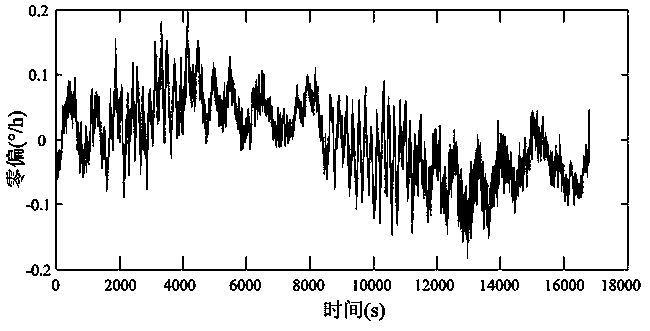
A fiber optic gyroscope and design system technology, applied in Sagnac effect gyroscopes, measuring devices, instruments, etc., can solve problems such as spectral shape differences and difficulties, eliminate gyroscope zero-bias oscillation, and improve product quality and production efficiency , the effect of good practical application value

Inactive Publication Date: 2014-03-26
FLIGHT AUTOMATIC CONTROL RES INST
View PDF9 Cites 12 Cited by
  • Summary
  • Abstract
  • Description
  • Claims
  • Application Information

AI Technical Summary

Problems solved by technology

[0004] However, there are still some problems in the design of high-precision fiber optic gyro depolarization optical path based on SFS light source, mainly in the parameter design of the depolarization optical path. The specific performance is: (1) The design of the depolarization structure is based on the coherence length of the optical signal For the SFS light source, due to the structural design of the light source, its output spectr...

Method used


Image

  • Fiber gyroscope depolarization light path design method and fiber gyroscope depolarization light path design system
  • Fiber gyroscope depolarization light path design method and fiber gyroscope depolarization light path design system
  • Fiber gyroscope depolarization light path design method and fiber gyroscope depolarization light path design system

Examples


Embodiment Construction

[0039] The present invention will be further described in detail below in conjunction with the accompanying drawings.

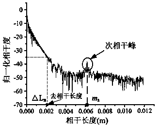
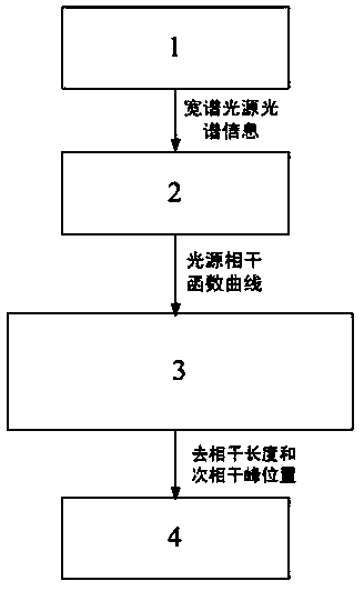
[0040] The design system of the fiber optic gyroscope depolarization optical path of the present invention includes an online measurement module 1 of a broadband light source spectrum, a calculation module 2 of a coherence function of a light source, a detection module 3 of a sub-coherence peak and a decoherence length of a coherence function, and a depolarization auxiliary design module 4 . Wherein, the online measurement module 1 measures the spectral data of the light source through a spectrometer, and stores it digitally. The light source coherence function calculation module 2 uses a coherence function calculation algorithm to calculate the coherence function of the light source, and obtains a coherence function curve. The detection module 3 judges the sub-coherence peak position of the light source and calculates the decoherence length of the light sour...


PUM


Abstract

The invention belongs to an optical design technique, and relates to a depolarization light path design method of a high-precision fiber gyroscope and a depolarization light path design system. The depolarization light path design method of the fiber gyroscope disclosed by the invention comprises an online measurement module of a wide-spectrum light source spectrum, a calculation module of a light source coherence function, a detection module of coherence function correlation peak and decoherence length and a depolarization scheme design module. The depolarization light path design method comprises the following steps: firstly, judging a correlation peak position of a light source and calculating the light source decoherence length by adopting a corresponding algorithm by online measurement of the spectrum data of each light source; providing design parameters of a depolarization scheme light path, wherein the design parameters comprise a length requirement on each polarization maintaining fiber in a depolarizer, a length requirement on a Y-waveguide tail fiber, and a shaft angle requirement of fusion of the polarization maintaining fiber in the depolarizer. By adopting the design method and the design system, accurate parameters are provided for the structure design of the depolarization light path, the depolarization light path capable of effectively eliminating a gyroscope zero oscillation phenomenon is designed, the product quality and the production efficiency are improved, and the design method and the design system have good practical application values.

Description

technical field [0001] The invention belongs to optical design technology, and relates to a high-precision optical fiber gyroscope depolarization optical path design method and a design system thereof. Background technique [0002] The suppression of polarization error in the fiber optic gyro optical path is one of the key technologies in the development of fiber optic gyro. Due to the inevitable introduction of bending, torsion and winding stress in the gyro optical path (especially the fiber optic ring) during the manufacturing process, the polarization state of the input light wave cannot be maintained in the optical path, and the change of the polarization state causes the output signal of the interferometer to rise. Falling will affect the performance of the gyro. At present, an important means to solve this problem is to use a polarization-maintaining fiber loop, and depolarize or depolarize the light wave input into the fiber coil. Among them, the depolarization sch...

Claims


Application Information

Patent Timeline
IPC IPC(8): G01C19/72
CPCG01C19/72G01C25/005
Inventor 谢良平李瑞王京献张斌马海全万洵
Owner FLIGHT AUTOMATIC CONTROL RES INST
Why Eureka
Try Eureka