Flow measuring device and method for non-full-flow pipe outlet

A technology of outlet flow and measuring device, which is applied to liquid level indicators for physical variable measurement, volume/mass flow generated by electromagnetic effects, etc., and can solve problems such as inconvenient portability, high price, and limited use of measuring equipment

Active Publication Date: 2014-03-26
LUANCHUAN LONGYU MOLYBDENUM IND
View PDF6 Cites 11 Cited by
  • Summary
  • Abstract
  • Description
  • Claims
  • Application Information

AI Technical Summary

Problems solved by technology

[0003] In view of the existing problems in the measuring device and method for measuring the flow at the outlet of a non-full flow pipeline in the prior art, the present invention proposes and discloses a hand-held portable device that can meet the requirements of measurement accuracy and measure the flow at the outlet of the pipeline under any pipeline cross-section conditions. The device and method for measuring the outlet flow of the seepage pipe of the tailings pond to solve and overcome the problems in the prior art that the use conditions of the measuring equipment are limited, the price is expensive, and it is not convenient to carry and patrol the measurement.

Method used


Image

  • Flow measuring device and method for non-full-flow pipe outlet
  • Flow measuring device and method for non-full-flow pipe outlet

Examples


Embodiment approach

[0019] Provide the embodiment of the present invention below in conjunction with accompanying drawing as follows:

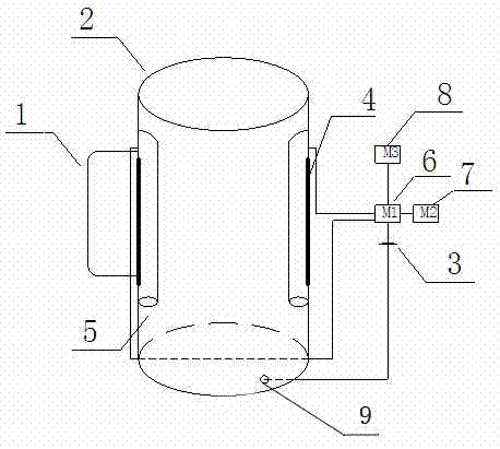
[0020] Such as figure 1 , figure 2 As shown, a non-full flow pipeline outlet flow measuring device according to the present invention is mainly composed of a handle 1, a measuring cup 2, a battery 3, a carbon electrode 4, a carbon electrode protection tube 5, a data processing module 6, and a display screen 7 , a thin film matrix keyboard 8; wherein the measuring cup 2 is a cylindrical container made of hard plastic with a sealed bottom and an upper opening; the bottom surface of the measuring cup 2 is provided with a wire connection point 9, which is connected to the upper end of the carbon electrode 4 through the battery 3 The handle 1 is installed on the outside of the measuring cup 2; the two carbon electrodes 4 are respectively bonded on the tube walls of the two carbon electrode protective tubes 5 which are protected by hard plastic tubes, and the carbon ...


PUM

PropertyMeasurementUnit
Sizeaaaaaaaaaa

Abstract

The invention relates to a flow measuring device and method for a non-full-flow pipe outlet. The flow measuring device and method for the non-full-flow pipe outlet are mainly used for measuring the flow of the seepage discharge pipe outlet of metal mine tailings. The flow measuring device for the non-full-flow pipe outlet is mainly composed of a handle cup (1), a measuring cup (2), a battery (3), carbon electrodes (4), carbon electrode protective tubes (5), a data processing module (6), a display screen (7) and a thin-film matrix keyboard (8). The flow measuring method comprises the steps that by measuring the liquid level heights of the measuring cup (2) in a period delta t1 and a period delta t2, the liquid level height of the measuring cup (2) on a medial axis line is determined, and the volume value of the liquid in the measuring cup (2) can be obtained by multiplying the value of the liquid level height on any one point of the medial axis line and the value of the base area of the measuring cup (2) together, wherein the flow value of the pipe outlet is a specific value between the value of the liquid volume and the timing time difference. The flow measuring device and method for the non-full-flow pipe outlet solve the problems in the prior art and are used for tailings of the beneficiation industry. The flowing measuring device has the advantages of being low in price, flexible in use, portable and still capable of guaranteeing the accuracy of the measurement data even if the hand-held measuring cup (2) has a certain tilt angle, and therefore measurement data are accurate.

Description

technical field [0001] The invention belongs to the technical field of flow measurement of drainage pipelines of tailing ponds in metal mines, and mainly relates to a device and method for measuring outlet flow of non-full flow pipelines. Background technique [0002] The safe operation of metal mine tailings ponds is inseparable from various seepage drainage facilities. The size of the seepage discharge flow reflects the seepage characteristics inside the dam body. The seepage characteristics are an important parameter for the safe operation of metal mine tailings, and regular inspections must be carried out. Seepage flow. At present, the non-full flow pipeline flow measurement device and method used in metal mine tailings ponds are electromagnetic flowmeters and liquid level gauges. According to the functional relationship, the cross-sectional area of ​​the flow can be obtained, and the outlet flow of the pipeline can be calculated by multiplying the cross-sectional area ...

Claims


Application Information

Patent Timeline
IPC IPC(8): G01F1/56G01F23/24
Inventor 邓金迪杨为群王贵中张磊郝旭军
Owner LUANCHUAN LONGYU MOLYBDENUM IND
Why Eureka
Try Eureka