Magnetoelectric tachometric transducer and test device thereof

A speed sensor and sensor technology, applied in the field of magnetoelectric sensors, can solve the problems of low sensor reliability, pollution, damage to the measured body, etc.

Inactive Publication Date: 2014-03-26
施董腾
View PDF4 Cites 22 Cited by
  • Summary
  • Abstract
  • Description
  • Claims
  • Application Information

AI Technical Summary

Problems solved by technology

The reliability of the sensor with this structure is low, and its internal structure is easily damaged under vibration or shock conditions.
In addition, the induction probe of the existing magnetoelectric speed sensor is exposed outside the housing, and there is a gap at the junction of the probe and the housing.
When the actual working temperature exceeds the normal range due to the failure of the measured body, the state of th...

Method used


Image

  • Magnetoelectric tachometric transducer and test device thereof
  • Magnetoelectric tachometric transducer and test device thereof
  • Magnetoelectric tachometric transducer and test device thereof

Examples


Embodiment Construction

[0016] The present invention will be further described below in conjunction with the accompanying drawings.

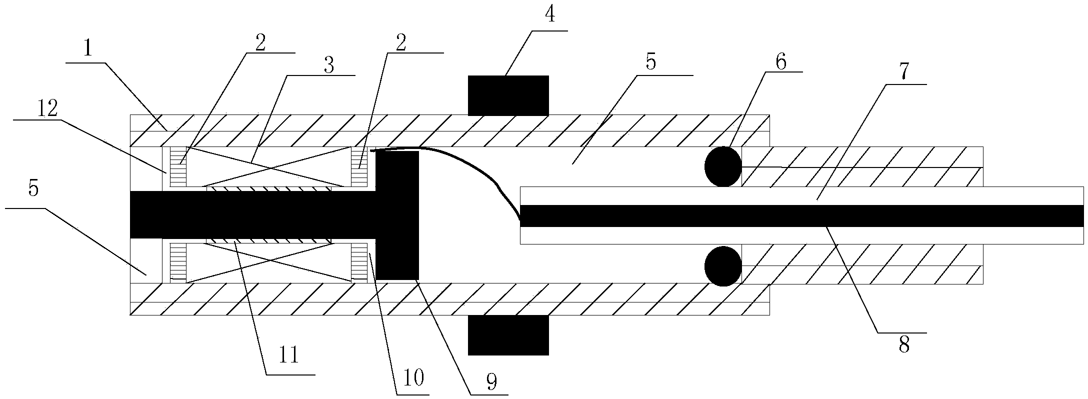
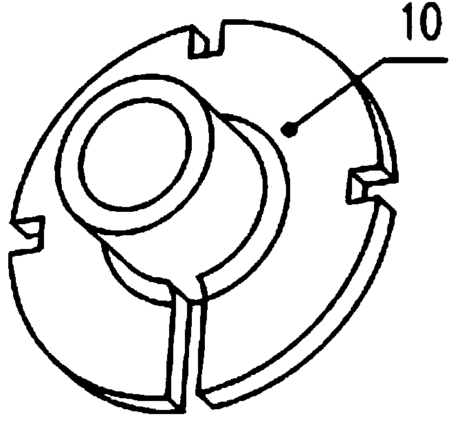
[0017] Such as figure 1 As shown, a magnetoelectric speed sensor includes a sensor injection molding body shell 1 and a sensor injection molding body, and the sensor injection molding body is provided with a coil skeleton 2, a coil 3, a nut 4, an epoxy resin filler 5, a sealing ring 6, and a sensor lead wire 7 , Iron core 9, inner half bobbin 10, heat shrink tube 11 and outer half bobbin 12. The coil 3 is wound in the middle of the bobbin 2, and the two ends of the bobbin 2 are provided with an inner half bobbin 10 and an outer half bobbin 12, and the small end faces of the inner half bobbin 10 and the outer half bobbin 12 extend into the middle of the I-shaped bobbin 2. In the through groove, the large end surfaces of the inner half bobbin 10 and the outer half bobbin 12 are in contact with the outer sides of both ends of the I-shaped bobbin 2; 10 and the small end ...


PUM


Abstract

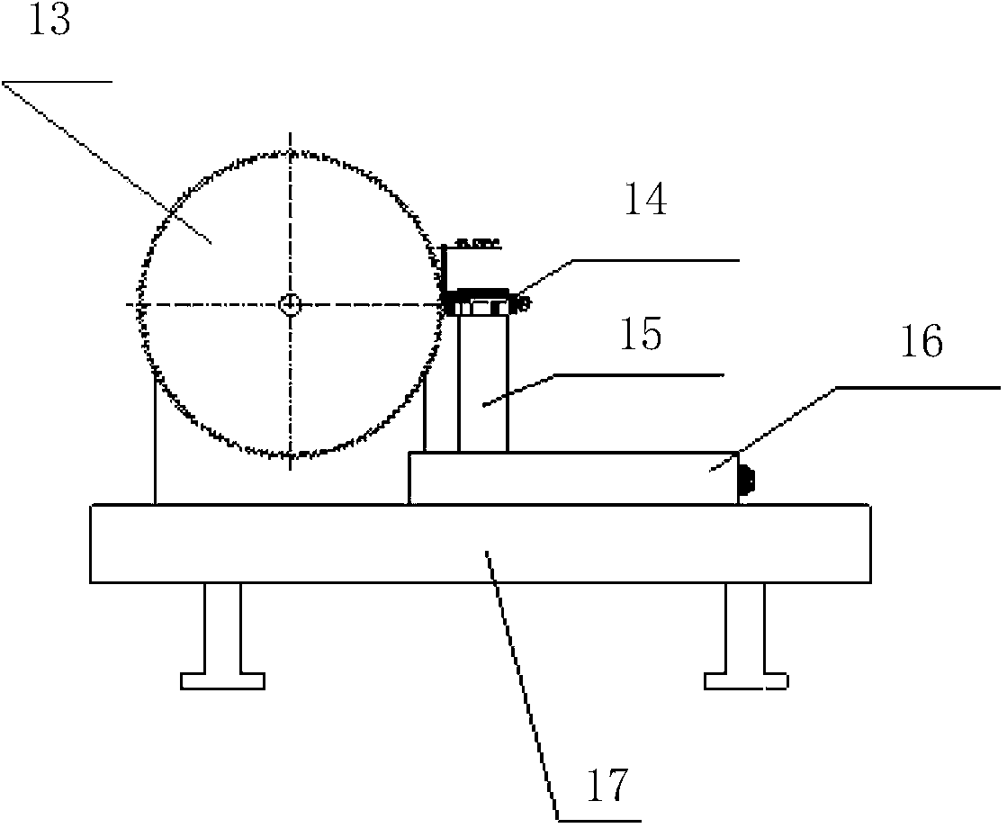
The invention discloses a magnetoelectric tachometric transducer and a test device thereof. The magnetoelectric tachometric transducer comprises an injection molding casing and an injection molding body. A coil frame, coils, an epoxy resin filler, a seal ring, a transducer lead, an iron core, an inner half reel, a shrinkable tube and an outer half reel are arranged in the injection molding body. The coils are wound in the middle of the coil frame. The inner half reel and the outer half reel are respectively arranged at two ends of the coil frame. The iron core is T-shaped. A lead core is arranged in the transducer lead. The epoxy resin filler is filled to the other space of the injection molding body. The test device of the magnetoelectric tachometric transducer comprises a test gear, a transducer holder, an air gap regulating slider and a worktable, wherein the test gear and the air gap regulating slider are arranged on the worktable, and the transducer holder is arranged on the worktable through the air gap regulating slider. The magnetoelectric tachometric transducer can be used for various industrial fields with combustible and explosive hazard gas, and is of stable internal structure.

Description

technical field [0001] The invention belongs to the technical field of magnetoelectric sensors, in particular to a magnetoelectric rotational speed sensor and a testing device thereof. Background technique [0002] The current magnetoelectric speed sensor is wound on magnetic steel or soft iron, and the coil is directly welded to the wire, so the manufacturing process is relatively low. The sensor with this structure has low reliability, and its internal structure is easily damaged under vibration or impact conditions. In addition, the induction probe of the existing magnetoelectric speed sensor is exposed outside the housing, and there is a gap at the junction of the probe and the housing. When the actual working temperature exceeds the normal range due to the failure of the measured body, the state of the sensor potting material will change from solid to liquid, and the liquid potting material will flow out along the gap and drop on the measured body. Pollution or even d...

Claims


Application Information

Patent Timeline
IPC IPC(8): G01P3/44G01P1/00G01P21/02
Inventor 施董腾郑虎凌刚
Owner 施董腾
Why Eureka
Try Eureka