General-purpose mechanical handle bar height adjustment mechanism with limiting function

A technology of height adjustment mechanism and manipulator, which is applied in the direction of mechanical control device, control/adjustment system, device for preventing/restricting/restoring the movement of parts of the control mechanism, etc. To solve problems such as poor comfort, to achieve good operating comfort, a wide selection of materials, and to ensure the effect of operating comfort

Inactive Publication Date: 2014-03-26
CHONGQING SHUNFANG MACHINERY MFG
View PDF0 Cites 0 Cited by
  • Summary
  • Abstract
  • Description
  • Claims
  • Application Information

AI Technical Summary

Problems solved by technology

Although this kind of mechanism meets the requirement of adjustable handle height, it has the following disadvantages: (1) When adjusting, the bolt on the adjustment mechanism needs to be taken out, and then reinserted into another screw hole to realize the height of the handle tube The adjustment is inconvenient to operate; (2) The adjustment gear is limited, because the minimum adjustment gear is the distance between two adjacent screw holes, the gear span is large, and the height cannot be adjusted finely, and the operating comfort is poor; ( 3) For the adjustment structure to play a role, it is necessary to weld the corresponding threaded sleeve on the handle seat to connect the handle pipe and the handle seat. The adjustment mechanism is complex and inconvenient to install

Method used


Image

  • General-purpose mechanical handle bar height adjustment mechanism with limiting function
  • General-purpose mechanical handle bar height adjustment mechanism with limiting function
  • General-purpose mechanical handle bar height adjustment mechanism with limiting function

Examples


Embodiment Construction

[0023] The present invention will be further described below in conjunction with the accompanying drawings and specific embodiments.

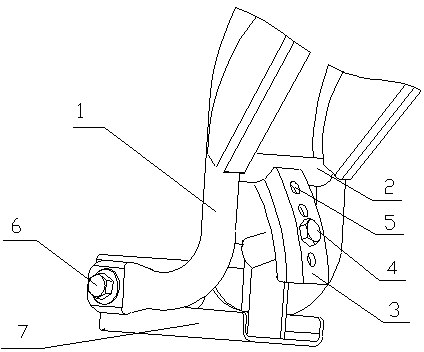
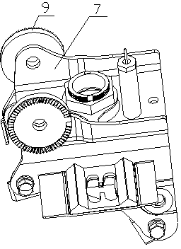
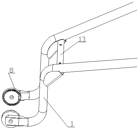
[0024] Such as figure 2 , image 3 and Figure 4 As shown, the height adjustment mechanism of the universal manipulator with limit in the present invention includes the left and right handle tubes 1 and the handle tube upper seat 7, and the middle positions of the left and right handle tubes 1 are connected together by the upper beam 13. The inner sides of the lower ends of the left and right handlebars 1 are respectively fixed with coaxial umbrella-shaped toothed discs 8 , and the tooth surfaces are located on the inner side and opposite to each other. The outer sides of the upper seat 7 of the handle tube are respectively fixed with fixed umbrella-shaped toothed discs 9, the tooth surfaces of the fixed umbrella-shaped toothed discs are located on the outside, and the left and right pairs of fixed umbrella-shaped toothed discs and movable u...


PUM


Abstract

The invention discloses a general-purpose mechanical handle bar height adjustment mechanism with a limiting function. The general-purpose mechanical handle bar height adjustment mechanism comprises a left handle bar tube, a right handle bar tube and a handle bar tube mounting base. The general-purpose mechanical handle bar height adjustment mechanism is characterized in that coaxial movable umbrella-shaped fluted discs are fixed to the lower end of the left handle bar tube and the lower end of the right handle bar tube respectively. Fixed umbrella-shaped fluted discs meshed with the movable umbrella-shaped fluted discs are fixed to the handle bar tube mounting base. A connecting bolt penetrates through the centers of the two sets of umbrella-shaped fluted discs, and the two sets of umbrella-shaped fluted discs in a meshed state are fastened through a locking mechanism. The tooth surface of each movable umbrella-shaped fluted disc is provided with a limiting boss, and each fixed umbrella-shaped fluted disc meshed with the movable umbrella-shaped fluted discs is provided with a limiting groove. The width of the limiting grooves is larger than that of the limiting bosses. The limiting bosses extend into the corresponding limiting grooves. Through the general-purpose mechanical handle bar height adjustment mechanism, the height of handle bars can be conveniently adjusted, and the general-purpose mechanical handle bar height adjustment mechanism is small in the tap position span, simple in structure and high in operation comfort degree.

Description

technical field [0001] The invention relates to a general machine, in particular to a height adjustment mechanism of a general manipulator. The adjustment mechanism has the advantages of simple structure, convenient adjustment and small adjustment gear. [0002] Background technique [0003] General machinery has a wide range, including various farming machines, lawn machines, snow blowers, etc. General-purpose machinery has a handle, which is located at the rear of the fuselage and mainly plays the role of controlling the machine. Due to the different heights of people, the height of the universal manipulator handle must have an adjustable function, so that people can operate the machine in a more comfortable way. Existing universal manipulator height adjustment mechanism such as figure 1 As shown, its structure is: a handle pipe 1 and a beam 2 connecting the two left and right handle pipes, and an adjustment mechanism 3 welded below the middle of the beam 2, and the...

Claims


Application Information

Patent Timeline
Patent Type & Authority Applications(China)
IPC IPC(8): G05G5/00
Inventor 杨家纯
Owner CHONGQING SHUNFANG MACHINERY MFG
Why Eureka
Try Eureka