Warning detection method
An alarm detection and fault detection technology, applied in the field of fault detection, can solve problems such as difficulty in unification and different detection mechanisms, and achieve the effect of saving system resources and improving system performance
- Summary
- Abstract
- Description
- Claims
- Application Information
AI Technical Summary
Problems solved by technology
Method used
Image

Examples
Embodiment Construction
[0025] In order to make the purpose, technical means and advantages of the present application clearer, the present application will be further described in detail below in conjunction with the accompanying drawings.
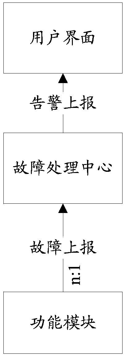
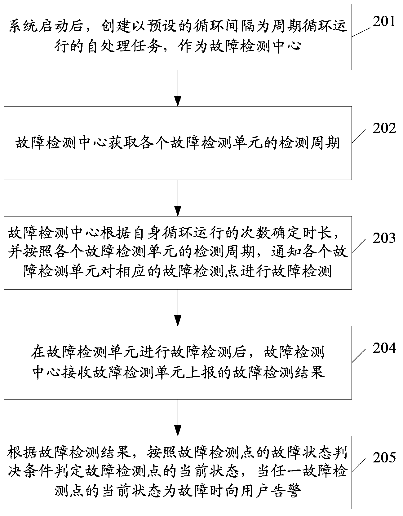
[0026] figure 2 It is a specific flow chart of the alarm detection method in this application, which is used to realize the fault detection of multiple detection points in the system. Wherein, a corresponding fault detection unit is provided corresponding to each fault check point in the system, and is used for realizing fault detection of the corresponding fault detection point. Such as figure 2 As shown, the method includes:
[0027] Step 201, after the system is started, create a self-processing task that runs at a preset cycle interval as a fault detection center.
[0028] The self-processing task can be realized by an infinite loop function, and the execution cycle of this function is a cycle interval. Wherein, the cycle interval can be set according ...
PUM
 Abstract
Description
Claims
Application Information
 - Generate Ideas
- Intellectual Property
- Life Sciences
- Materials
- Tech Scout
- Unparalleled Data Quality
- Higher Quality Content
- 60% Fewer Hallucinations
Browse by: Latest US Patents, China's latest patents, Technical Efficacy Thesaurus, Application Domain, Technology Topic, Popular Technical Reports.
© 2025 PatSnap. All rights reserved.Legal|Privacy policy|Modern Slavery Act Transparency Statement|Sitemap|About US| Contact US: help@patsnap.com