System and method for database lock with reference counting

a database and reference counting technology, applied in the field of database lock with reference counting, can solve the problems of future use of data, data can become logically incorrect, and types of problems, and achieve the effects of efficient administration, convenient compatibility of operations, and efficient operation

Active Publication Date: 2005-10-20
MICROSOFT TECH LICENSING LLC
View PDF10 Cites 31 Cited by
  • Summary
  • Abstract
  • Description
  • Claims
  • Application Information

AI Technical Summary

Benefits of technology

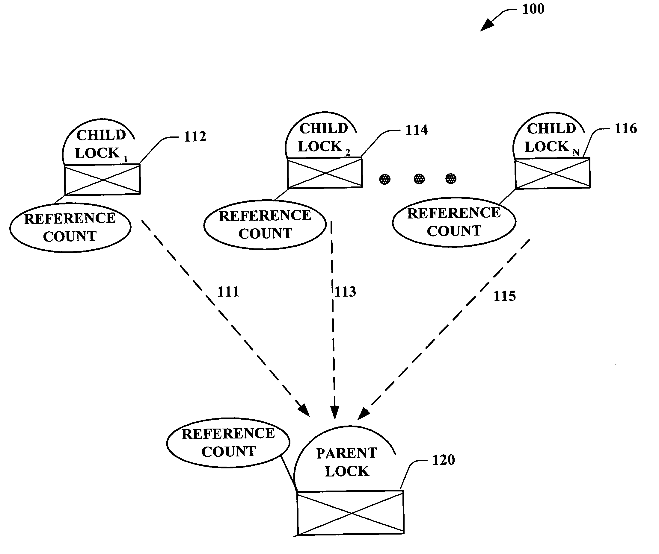
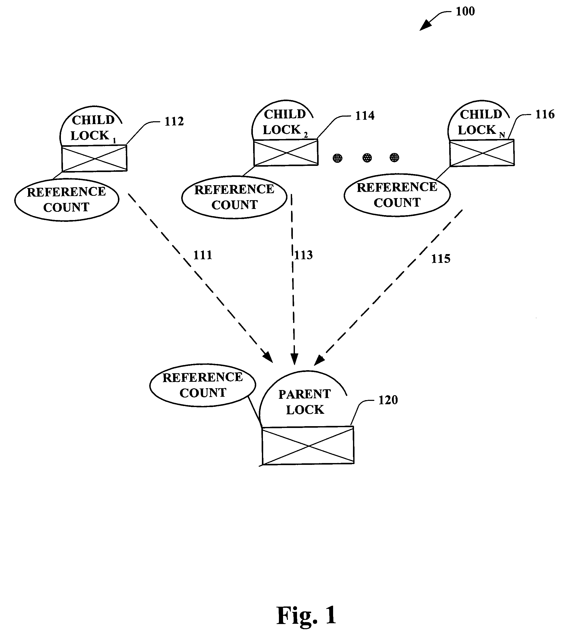
[0011] The present invention provides for systems and methods of supplying a database with a parent-child lock hierarchy arrangement, such that each lock contains sufficient information to determine its own life time. Such information can be supplied via a reference count of the locks, wherein upon release of all child locks associated with a parent lock, the parent lock can also subsequently be released. This framework enables a higher degree of transaction concurrency in a database, and mitigates an over locking thereof, thus conserving system resources. Accordingly, the database performance can be increased while improving an end-user experience.
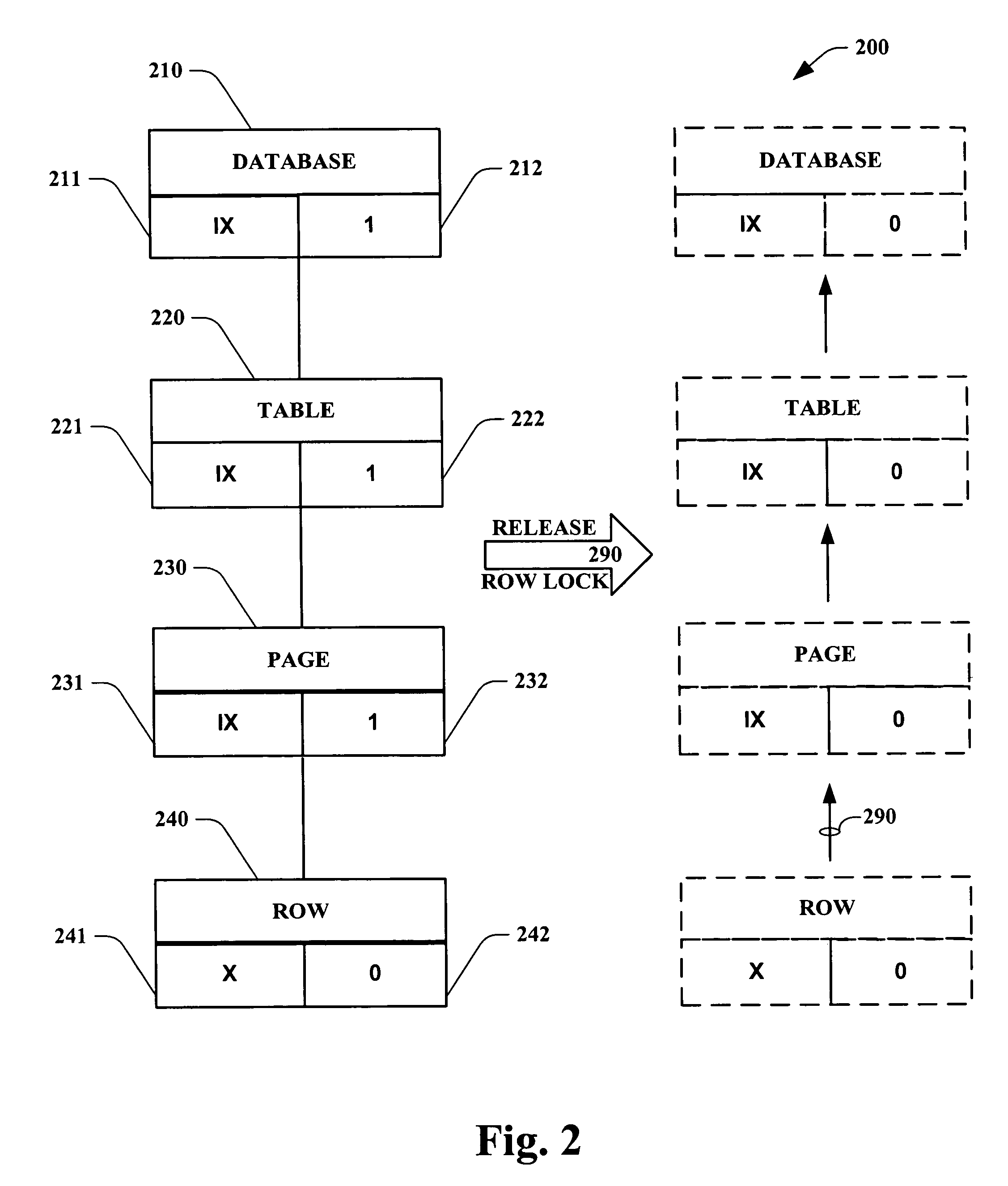
[0014] In a related aspect of the present invention the lock manager guards a logical consistency of the database during performance of concurrent transactions performed thereon, wherein as the child locks are removed, then the parent (e.g., an intent lock) of such child locks can also be removed. For example, as a transaction scans data it can acquire locks for certain resources. When such scanning is completed, a methodology according to the present invention can remove not only child locks at a low level, but also the higher parent level locks structures. As child locks are requested at a lower level of the hierarchy, parent locks can be obtained at a high level of the hierarchy, and as the child locks are removed, the parent child can be removed thereafter.
[0015] A further aspect of the present invention provides for a lock monitoring and reference system, wherein as each lock is being released, a number of locks referenced by an associated parent lock of the released lock can be decremented by one. Accordingly, once the number of locks associated with the parent lock reaches zero, the parent lock can then be removed. In an exemplary aspect, a pointer can guide the release operation from each child lock to its respective parent. Such enables an efficient operation for releasing locks that are no longer required.
[0016] The lock manager of the present invention can further allow sub page level locks across concurrent transactions. Such lock manager can be visible to all transactions, and based on a normal concurrency of operation a determination can be made whether a lock on a particular resource (e.g., a row level locking) can be granted. As such, the lock manager can facilitate compatibility of operations across concurrent transactions, and effectively administer logical considerations during modifications of the database.

Problems solved by technology

If such locking mechanisms do not operate properly, data can become logically incorrect, and future use of the data can produce unexpected results.
In addition, multiple transactions trying to use the same data concurrently can give rise to several different types of problems referred to as concurrency problems.
Such problems can cause updates of data by one application to be lost or overwritten by another application.
This can also result in reads of data which should be the same, not being the same.
Further problems can result from applications using copies of data, which are then changed by a later application.
Such types of locks can consume system resources and have associated costs.
If many rows are involved in a transaction which needs to lock portions of the database to ensure concurrency, a significant amount of system resources can be consumed.
The problems associated with the lock control can include a trade off between the transaction concurrence based on the granularity of the locked data unit and the overhead in the lock control processing.
Moreover, for such systems over-locking can create problems, wherein a transaction acquires more locks than is necessary and / or holds locks for longer than is required.
Put differently, resources can be locked that need not be locked, thus becoming unavailable to other transactions.
At the same time, minimizing the locks that are retained during a transaction's operation can pose problems when a lock hierarchy is involved.
In such cases, even if the row lock is simply discarded prior to the completion of the transaction, discarding associated parent resources or locks can be a challenging task.
Furthermore, even if such associated parent locks are identified and removed, they still may need to be reacquired immediately for subsequent operations, hence creating an inefficient procedure

Method used


Image

  • System and method for database lock with reference counting
  • System and method for database lock with reference counting
  • System and method for database lock with reference counting

Examples


Embodiment Construction

[0027] The present invention is now described with reference to the drawings, wherein like reference numerals are used to refer to like elements throughout. In the following description, for purposes of explanation, numerous specific details are set forth in order to provide a thorough understanding of the present invention. It may be evident, however, that the present invention may be practiced without these specific details. In other instances, well-known structures and devices are shown in block diagram form in order to facilitate describing the present invention.

[0028] As used in this application, the terms “component,”“handler,”“model,”“system,” and the like are intended to refer to a computer-related entity, either hardware, a combination of hardware and software, software, or software in execution. For example, a component can be, but is not limited to being, a process running on a processor, a processor, an object, an executable, a thread of execution, a program, and / or a c...


PUM


Abstract

Systems and methodologies are provided in a lock hierarchy arrangement wherein upon release of all child locks associated with a parent lock, then such parent lock is also released. The present invention supplies each lock with sufficient information to determine its own life time. Such framework enables a higher degree of transaction concurrency in a database, and mitigates an over locking thereof, thus conserving system resources.

Description

TECHNICAL FIELD [0001] The present invention relates generally to locking mechanism in databases, and more particularly to systems and methods that facilitate locking of resources during performance of concurrent transactions by employing a reference count in parent-child lock configurations. BACKGROUND OF THE INVENTION [0002] Increasing advances in computer technology (e.g., microprocessor speed, memory capacity, data transfer bandwidth, software functionality, and the like) have generally contributed to increased computer application in various industries. Ever more powerful server systems, which are often configured as an array of servers, are often provided to service requests originating from external sources such as the World Wide Web, for example. As local Intranet systems have become more sophisticated thereby requiring servicing of larger network loads and related applications, internal system demands have grown accordingly as well. As such, much business data is stored in ...

Claims


Application Information

Patent Timeline
Patent Type & Authority Applications(United States)
IPC IPC(8): G06F17/30
CPCG06F17/30362G06F16/2343
Inventor BAILEY, STEVENNETTLETON, DAVID J.
Owner MICROSOFT TECH LICENSING LLC
Why Eureka
Try Eureka