
Traffic intersection intelligent monitoring method

A traffic intersection and intelligent monitoring technology, which is applied in the direction of traffic flow detection and traffic signal control, can solve problems such as high cost, inability to humanize the configuration of signal lights, and defects in pedestrian supervision, so as to achieve optimal configuration, reduce facility costs, and improve Regulatory Efficiency Effects

Active Publication Date: 2014-03-26
SUZHOU HB AI TECH RES&DEV CO LTD
View PDF5 Cites 63 Cited by
  • Summary
  • Abstract
  • Description
  • Claims
  • Application Information

AI Technical Summary

Problems solved by technology

[0002] At present, traffic violation monitoring usually adopts the method of installing electromagnetic induction, pressure sensing or light sensing devices on the roadside or lane of the traffic intersection to detect the position information of the vehicle, or adopts the traditional ground induction coil detection method. Rectangular slots are cut in front of and behind the parking line on the driveway, and then the induction coil or induction rod is ambush to detect the location information of the vehicle. The system judges whether the vehicle has violated the rules through the analysis of the obtained location information. This kind of traffic violation monitoring is not only cost-effective High, and there is a certain degree of difficulty in construction. At the same time, there are certain defects in the supervision of pedestrians, and there is a lack of interaction with the traffic signal light control system. Humanized configuration of signal lights cannot be performed under special circumstances.

Method used


Image

  • Traffic intersection intelligent monitoring method
  • Traffic intersection intelligent monitoring method
  • Traffic intersection intelligent monitoring method

Examples


Embodiment Construction

[0040] The present invention will be further described in detail below in conjunction with the accompanying drawings, so that those skilled in the art can implement it with reference to the description.

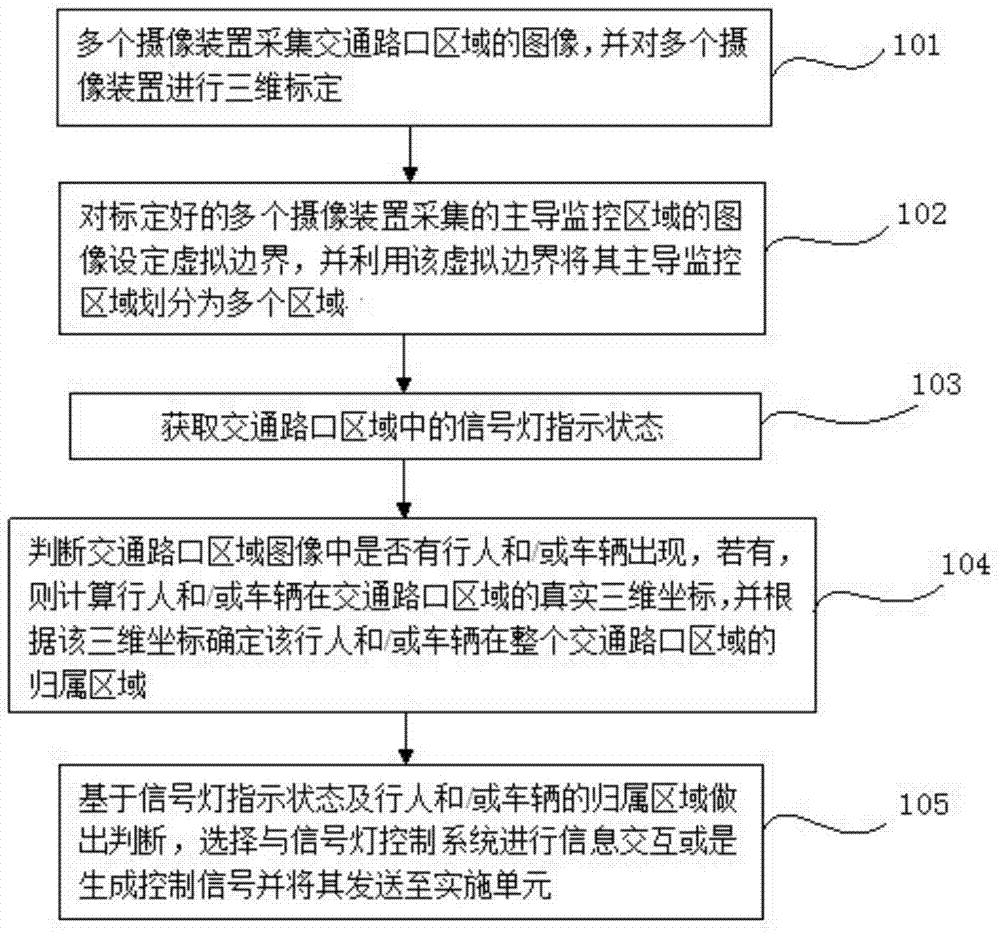
[0041] like figure 1 As shown, the present invention discloses a kind of traffic intersection intelligent monitoring method, and it comprises the following steps:

[0042] Step 1 101, collect images of the traffic intersection area through multiple camera devices, and perform three-dimensional calibration on the multiple camera devices, so as to establish the relationship between the image pixel position of each object in the image and the real three-dimensional coordinates of each object in the traffic intersection area corresponding relationship;

[0043] Step 2 102: Set a virtual boundary for the images of the dominant monitoring area collected by the calibrated multiple camera devices, and use the virtual boundary to divide the dominant monitoring area into multiple area...


PUM


Abstract

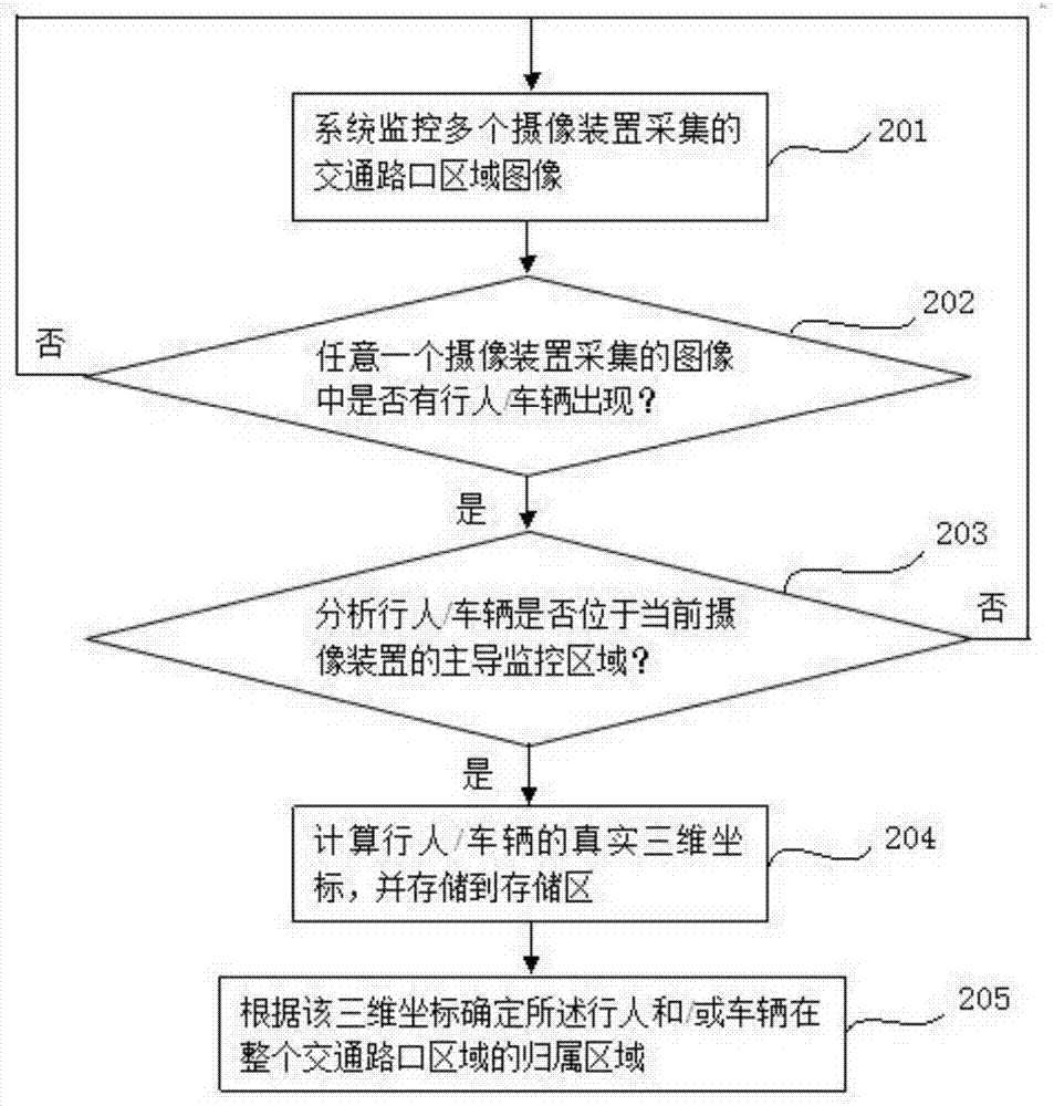
The invention discloses a traffic intersection intelligent monitoring method. The traffic intersection intelligent monitoring method comprises the steps of: firstly, acquiring images of a traffic intersection region through multiple camera devices and performing three-dimensional calibration on the multiple camera devices; setting virtual borders for images of a main monitoring region acquired by the well-calibrated camera devices and dividing the main monitoring region into multiple regions by utilizing the virtual borders; obtaining an indicating state of a signal lamp in the traffic intersection region; judging whether a pedestrian and / or a vehicle appear or appears in the images of the traffic intersection region, if so, calculating a real three-dimensional coordinate of the pedestrian and / or the vehicle in the traffic intersection region through a central processing unit and determining the attributive region of the pedestrian and / or the vehicle in the whole traffic intersection region based on the three-dimensional coordinate; judging by the central processing unit based on the indicating state of the signal lamp and the attributive region of the pedestrian and / or the vehicle. The traffic intersection intelligent monitoring method not only reduces facility cost for traffic violation supervisory control, but also optimizes configuration of the signal lamp through information exchange with a signal lamp control system.

Description

technical field [0001] The invention relates to an intelligent monitoring method for a traffic intersection. Background technique [0002] At present, traffic violation monitoring usually adopts the method of installing electromagnetic, pressure or light sensing devices on the roadside or lane of the traffic intersection to detect the position information of the vehicle, or adopts the traditional ground sensing coil detection method. Rectangular slots are cut in front of and behind the parking line on the driveway, and then the induction coil or induction rod is ambush to detect the location information of the vehicle. The system judges whether the vehicle has violated the rules through the analysis of the obtained location information. This kind of traffic violation monitoring is not only cost-effective High, and there is a certain degree of difficulty in construction, and there are also certain defects in the supervision of pedestrians, and the lack of interaction with the...

Claims


Application Information

Patent Timeline
IPC IPC(8): G08G1/01G08G1/07
Inventor 叶珍凤
Owner SUZHOU HB AI TECH RES&DEV CO LTD
Learn More