Supercharge Your Innovation With Domain-Expert AI Agents!

Moisture separator reheater and nuclear power plant

A steam-water separation and reheater technology, which is applied in nuclear power generation, heat exchange equipment, lighting and heating equipment, etc., can solve the problems of equipment miniaturization and inability to effectively use the steam-water separation reheater, and achieve the effect of miniaturization

Inactive Publication Date: 2014-03-26
KK TOSHIBA
View PDF2 Cites 0 Cited by
  • Summary
  • Abstract
  • Description
  • Claims
  • Application Information

AI Technical Summary

Problems solved by technology

[0008] However, in the above-mentioned conventional steam-water separation reheater, when a partition plate is provided in the main body container, a space that cannot be effectively used for the function of the steam-water separation reheater such as the above-mentioned ineffective part is generated.
Therefore, increasing the tube bundle in order to ensure the necessary heat transfer area is the cause of the increase in the size of the steam-water separation reheater.
In addition, there is a tendency to increase the size of the steam-water separation reheater along with the increase in the capacity of nuclear power plants, but it is necessary to reduce the size of the constituent equipment

Method used


Image

  • Moisture separator reheater and nuclear power plant
  • Moisture separator reheater and nuclear power plant
  • Moisture separator reheater and nuclear power plant

Examples


no. 1 Embodiment approach )

[0030] [structure]

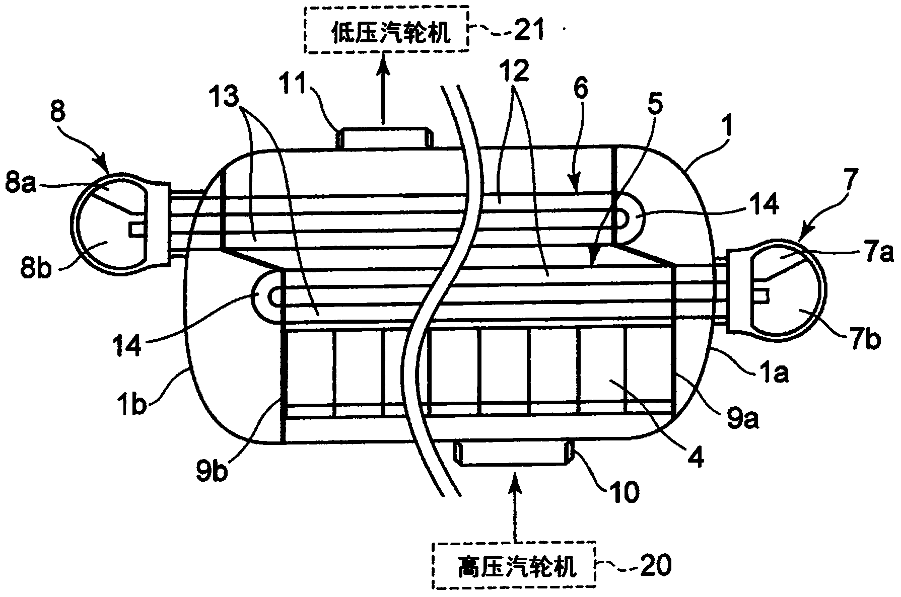
[0031] figure 1 It is a front schematic configuration view showing the first embodiment of the steam-water separator reheater according to the present invention.

[0032] The steam-water separation reheater of this embodiment is installed in nuclear power generation equipment, such as figure 1 As shown, the moisture of the humid steam discharged from the high-pressure steam turbine 20 is separated, and the heated steam separated from the moisture is reheated by exchanging heat with the heating fluid, and the reheated heated steam is supplied to the low-pressure steam turbine 21 and the like. .

[0033] The steam-water separation reheater of the present embodiment is provided with: a cylindrical main body container 1 which is arranged laterally in a horizontal manner in the longitudinal direction in an installed state with both ends in the longitudinal direction sealed by heads 1a and 1b; The lower steam-water separator 4 in the container 1; the first he...

no. 2 Embodiment approach )

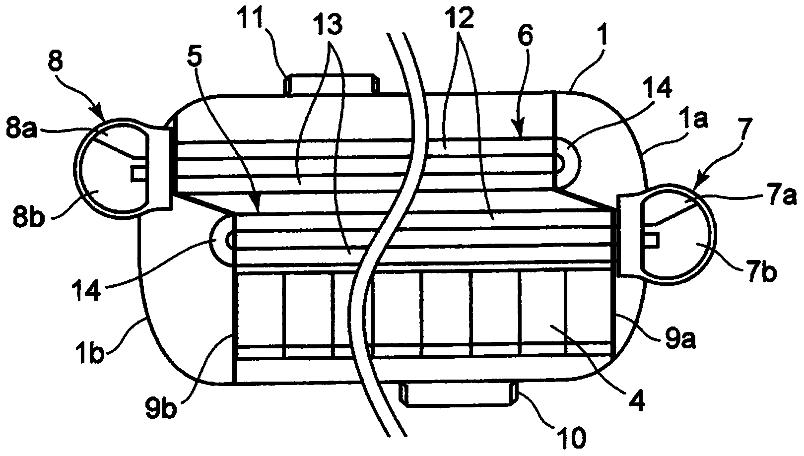
[0063] figure 2 It is a front schematic configuration view showing a second embodiment of the steam-water separator reheater according to the present invention. In addition, in the following embodiment, the same code|symbol is attached|subjected to the same part as the said 1st Embodiment, and overlapping description is abbreviate|omitted.

[0064] Such as figure 2 As shown, in the steam-water separator reheater of this embodiment, on the basis of the structure of the above-mentioned first embodiment, the first heater head 7 and the second heater head 8 are arranged to pass through the sealing heads 1a and 1b respectively. And it enters into the main body container 1 until it reaches the outer surface of a pair of partition plates 9a, 9b.

[0065] Therefore, the first heater head 7 and the second heater head 8 are installed in a state where only a part is exposed from the heads 1a, 1b.

[0066] Thus, according to the present embodiment, the first heater head 7 and the sec...

no. 3 Embodiment approach )

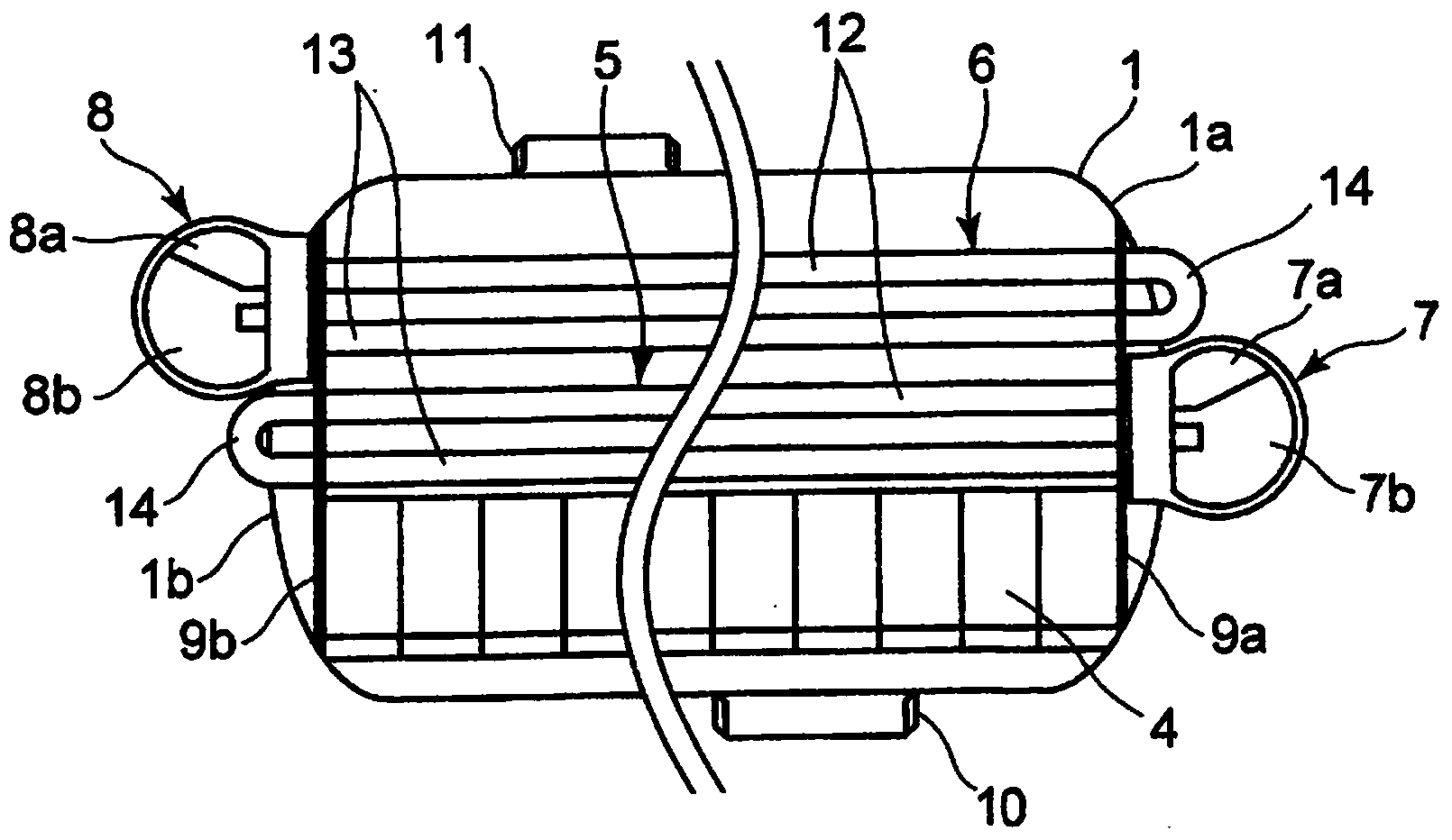
[0068] image 3 It is a front schematic configuration view showing a third embodiment of the steam-water separator reheater according to the present invention.

[0069] Such as image 3 As shown, in the steam-water separator reheater of this embodiment, on the basis of the structure of the above-mentioned second embodiment, the first heat transfer piping group 5 and the ineffective part of the second heat transfer piping group 6, that is, the curved pipe portion 14 are respectively Set on the outside of the head 1a, 1b. A pair of partitions 9 a, 9 b are provided in each of the heads 1 a, 1 b so that the heated vapor does not flow into the curved pipe portion 14 .

[0070] The first heater head 7 and the curved pipe portion 14 of the second heat transfer piping group 6 are arranged adjacent to each other in the vertical direction. Similarly, the curved pipe portion 14 of the first heat transfer piping group 5 and the second heater head 8 are arranged adjacent to each other i...


PUM


Abstract

An object thereof is to provide a moisture separator reheater capable of ensuring a required heat transfer area with short heat exchanger tubes to thereby allow reduction in the size thereof, and a nuclear power plant.. According to one embodiment, there is provided a moisture separator reheater comprising: a horizontal cylindrical type body drum having a steam inlet for introducing thereinside steam to be heated at its lower portion and a steam outlet for exhausting therefrom the steam at its upper portion; end plates that seal both end portions of the body drum in a longitudinal direction thereof; a moisture removal section that removes moisture in the steam distributed inside the body drum; a heat transfer tube group disposed above the moisture removal section, heating fluid for heating the steam being distributed in the heat transfer tube group; a heater header that supplies the heating fluid to the heat transfer tube group and exhausts outside the heating fluid that has been heat exchanged with the steam; and a partition plate disposed inside the body drum so as to guide the steam from the moisture removal section to the heat transfer tube group; the heat transfer tube group including a plurality of heat transfer tubes each having a forward passage part, a backward passage part, and a bent tube part, the forward and the backward passage parts extending in longitudinal direction of the body drum and the bent tube part connecting the forward and the backward passage parts, the bent tube part being provided outside the end plates.

Description

technical field [0001] Embodiments of the present invention relate to a steam-water separation reheater and a nuclear power plant that separate and heat moisture from heated steam. Background technique [0002] Moisture Separator Reheater (MSR: Moisture Separator Reheater) installed in nuclear power plants, etc. has the function of separating the moisture of the humid steam discharged from the high-pressure steam turbine, and heats the heated steam and the heating fluid after the moisture is separated. Swap these two functions while reheating the function. As the heating fluid, for example, main steam from a steam generator, extraction steam from a high-pressure turbine, or the like is used. Then, the heated steam reheated by the steam-water separation reheater is supplied to a low-pressure steam turbine and the like. [0003] In the steam-water separation reheater, when the heater head is installed outside the main vessel as a design of the pressure vessel, etc., the open...

Claims


Application Information

Patent Timeline
Patent Type & Authority Applications(China)
IPC IPC(8): G21C15/16
CPCF16T1/34F22B37/266F22B37/268Y02E30/00F22G3/00G21D1/02F28D2021/0054F28F9/0202F28F9/22F28F2009/0285F28F2009/226
Inventor 栗原祥吾吉村浩一
Owner KK TOSHIBA
Features
  • R&D
  • Intellectual Property
  • Life Sciences
  • Materials
  • Tech Scout
  • Unparalleled Data Quality
  • Higher Quality Content
  • 60% Fewer Hallucinations
Learn More