Inductor and manufacturing method

A manufacturing method and inductor technology, applied in the field of inductors, can solve the problems of increasing the number of parts, complicating the manufacturing process, and increasing production costs, and achieve the effect of ensuring electrical insulation

Active Publication Date: 2014-03-26
ALPS ALPINE CO LTD
View PDF13 Cites 3 Cited by
  • Summary
  • Abstract
  • Description
  • Claims
  • Application Information

AI Technical Summary

Problems solved by technology

Here, in Patent Document 5, although an insulating sheet of a different body is interposed between the magnetic core and the terminal, such a structure has problems such as an increase in the number of parts, an increase in production cost, and a complication of the manufacturing process.

Method used


Image

  • Inductor and manufacturing method
  • Inductor and manufacturing method
  • Inductor and manufacturing method

Examples


Embodiment Construction

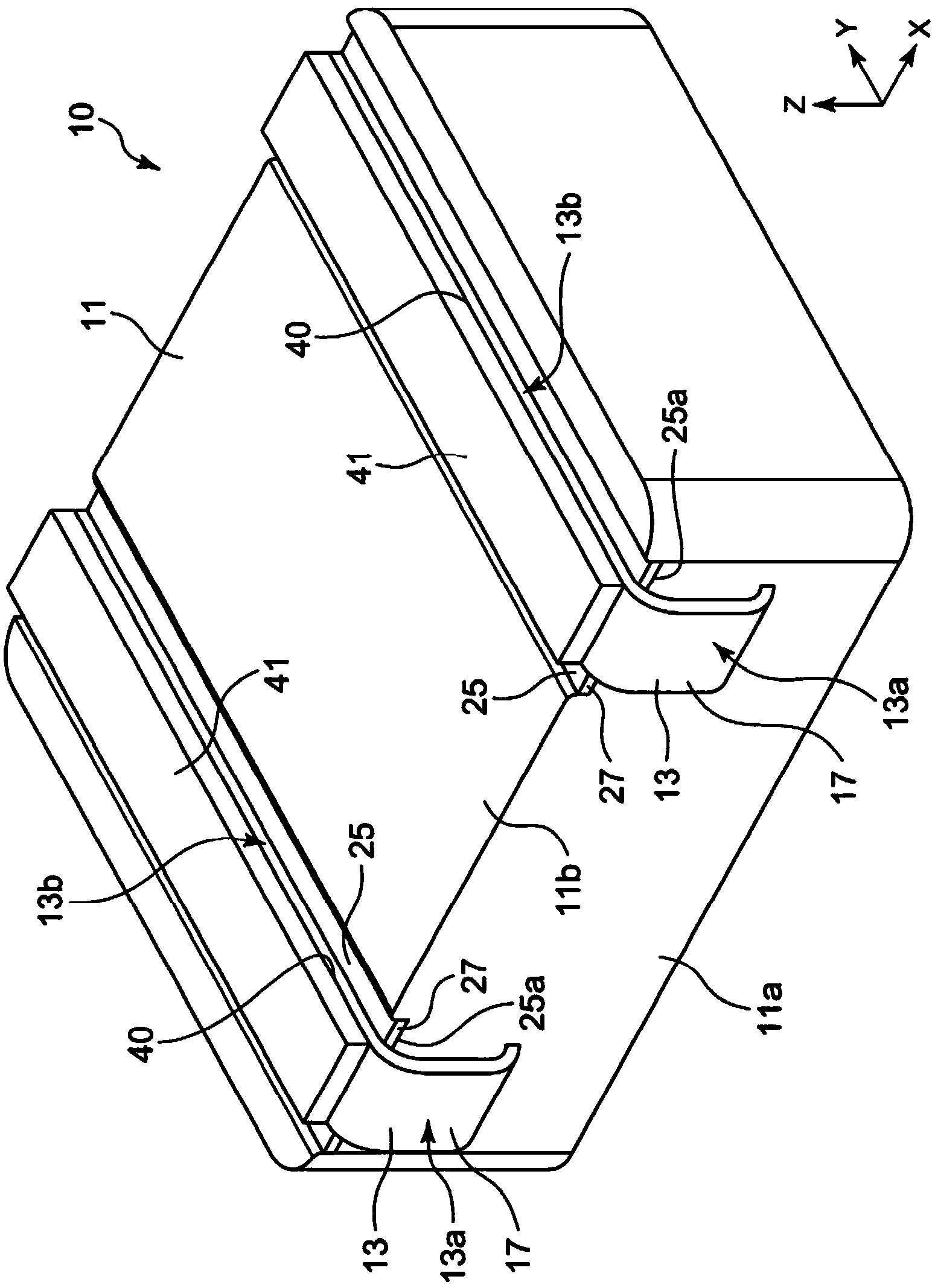
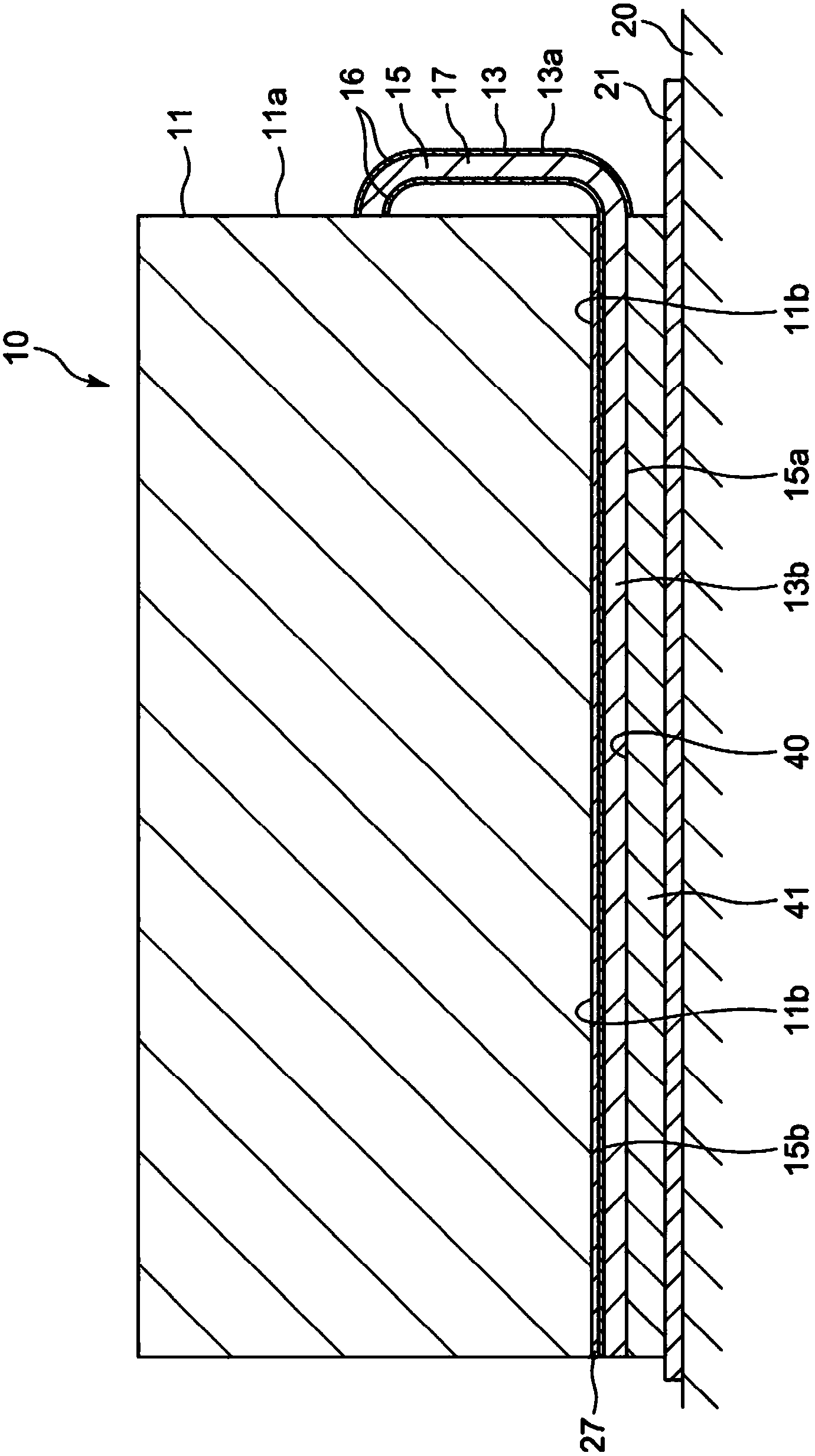
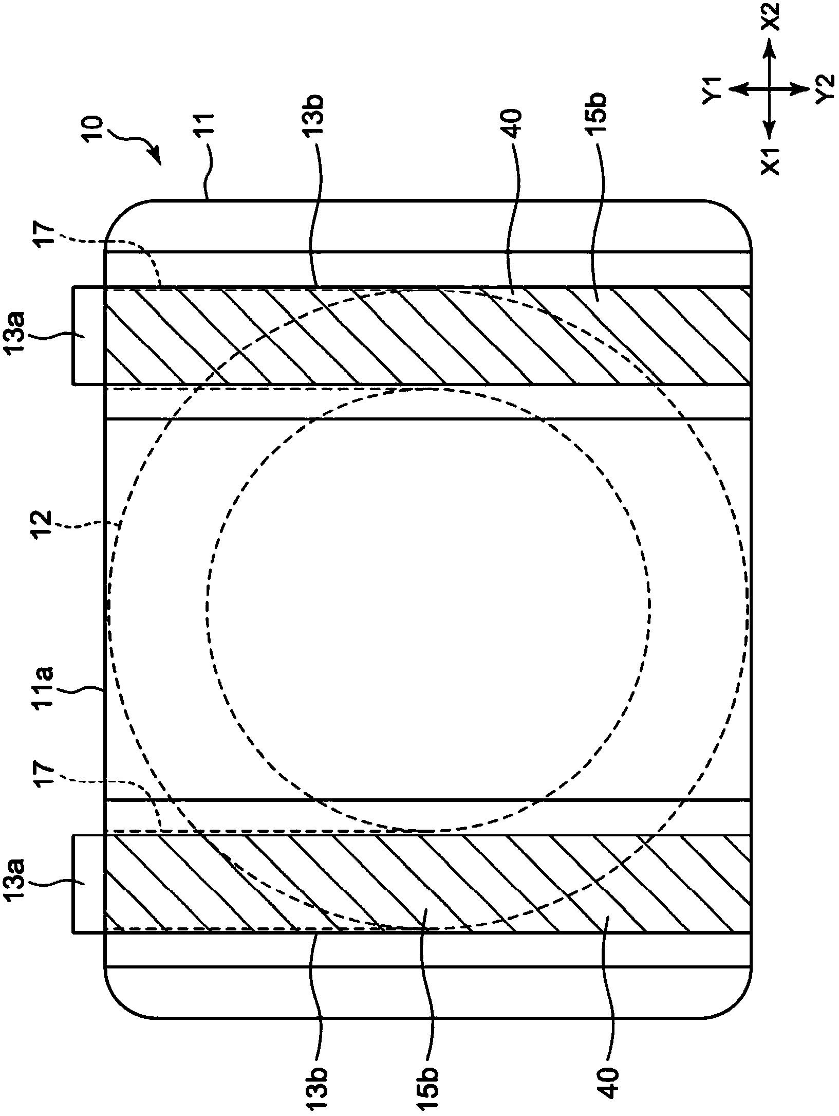
[0065] figure 1 is a perspective view of the inductor in the first embodiment, figure 2 will be figure 1 A longitudinal sectional view of the state where the inductor is mounted on the substrate shown, image 3 is a rear view (bottom view) of the inductor in this embodiment, Figure 4 (a) shows an enlarged cross-sectional view of a terminal located on a side surface of a magnetic core, Figure 4 (b) shows an enlarged sectional view of a terminal located on the lower surface of the magnetic core, Figure 4 (c), Figure 4 (d) means Figure 4 Modified example of (b). It should be noted that, in figure 2 In the sectional view of , the partially exposed cross-section of the original coil 12 is omitted.

[0066] Such as figure 1 , figure 2 , image 3 As shown, an inductor 10 has a magnetic core 11 , a coil 12 and a plurality of terminals 13 , 13 .

[0067] The magnetic core 11 is obtained by compression-molding a plurality of Fe-based amorphous alloy (Fe-based metalli...


PUM


Abstract

The invention aims to provide an inductor preventing welding pin formation on a side face when welding with a welding pad and a manufacturing method of the inductor. The inductor is provided with a coil; a magnetic iron core (11) inside provided with the coil; a terminal (13) led from a side face (11a) of the magnetic coil from the lower surface (11b) of the magnetic iron core. The coil is formed by coiling a covering conductor covering the outer peripheral surface of the conductor (15) in an insulating manner. The covering conductor (17) serving as a terminal (13) is led from the coil towards the side face of the magnetic iron core and the lower surface of the magnetic iron core. And the covering part (16) of the lower surface (15a) of the conductor is stripped off in a condition that the covering part (16) having electric insulation performance remains on the upper surface (15b) of the conductor arranged opposite to the magnetic iron core in a position of the lower surface of the magnetic iron core, so that the conductor (15) is exposed and an electrode face (40) is formed.

Description

technical field [0001] The present invention relates to an inductor having a coil, a magnetic core in which the coil is arranged, and terminals drawn out to the outer surface of the magnetic core, and a method for manufacturing the same. Background technique [0002] Inventions related to the structure of inductors are disclosed in the following patent documents. The coil is embedded in the magnetic core. In Patent Document 1 or Patent Document 2, a terminal separate from the coil and electrically connected to the coil is formed on the side surface of the magnetic core. [0003] In Patent Document 3 to Patent Document 5, the conductor is directly drawn out from the coil to the outside of the magnetic core. In all cases, the covering portion of the entire terminal drawn out of the magnetic core is peeled off to expose the conductor (see column [0016] of Patent Document 3, column [0018] of Patent Document 4, and column [0013] of Patent Document 5). . It should be noted that...

Claims


Application Information

Patent Timeline
Patent Type & Authority Applications(China)
IPC IPC(8): H01F17/04H01F27/29H01F27/30H01F41/00
Inventor 樱井胜松井政夫松井和彦川濑恭一丸山智史安彦世一水岛隆夫小岛章伸村上润一松山英一郎荒木庆一佐藤祐辅行方美奈子
Owner ALPS ALPINE CO LTD
Why Eureka
Try Eureka