


Quick Research
Generate reliable direction feasibility study reports for your R&D in just a few steps.

Technical Q&A
Discover and master advanced knowledge NOW. Basics, ideas, possibilities, all at once.

Find Solutions
As an expert in R&D theories, this can generate solutions to your technical problems instantly.

Evaluate Feasibility
Analyze your overall solution with one click, know your potential R&D risks in advance.

Monitor Landscape
Get weekly tech updates, stay abreast of the latest tech innovations and key insights.
Transformer heat dissipation device
A cooling device and transformer technology, applied in the direction of transformer/inductor cooling, etc., can solve the problems of poor heat dissipation of transformers, loss of air volume, and inability to cool down, etc., and achieve the goal of omitting technical elements, saving packaging costs, and overcoming technical prejudices Effect
- Summary
- Abstract
- Description
- Claims
- Application Information
AI Technical Summary
Problems solved by technology
Method used
Image

Examples
Example Embodiment
[0037] Example 1
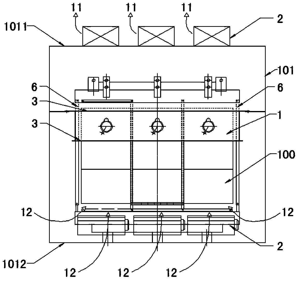
[0038] Please refer to figure 1 , figure 1 It is a structural schematic diagram of Embodiment 1 of the transformer cooling device of the present invention.
[0039] The air duct 1 surrounds one third of the transformer body 100 .
[0040] The air duct 1 surrounds the upper section of the transformer body 100 .
[0041] The following is a comparison of the data obtained through experiments in this example and the data described in the packaging method experiment in the background technology. The temperature rise data under the rated load loss of 3 hours, the cost of the heat sink (material and labor), and the packaging efficiency are listed respectively. Comparative data:
[0042]
[0043] Compared with the existing cooling device, the technical solution described in Embodiment 1 omits the technical feature of the upper air duct pipe, and the length of the air guide pipe 1 is only 1 / 3 of the original.
[0044] Experimental data show that, compared wit...
Example Embodiment
[0045] Example 2
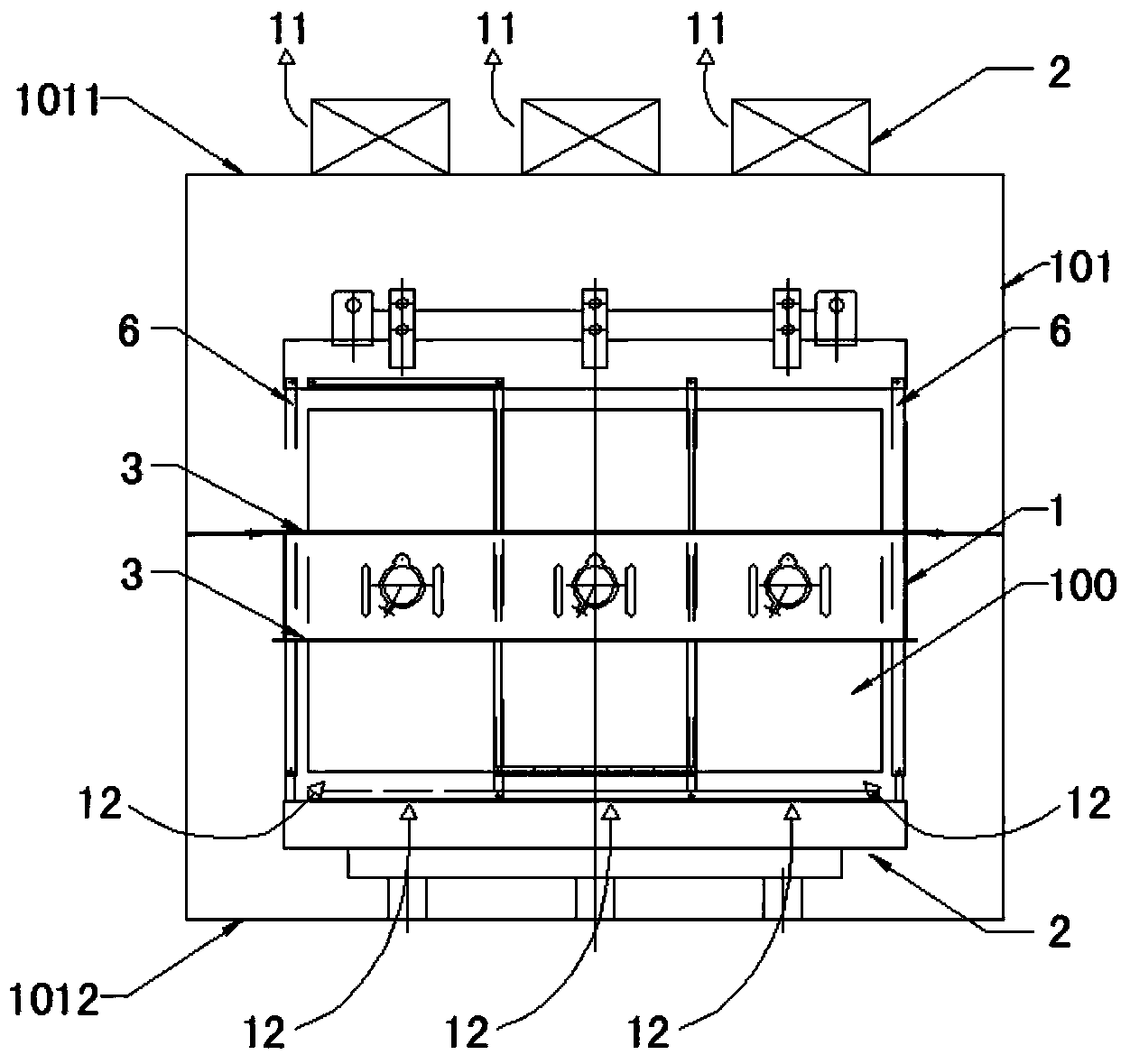
[0046] Please refer to figure 2 , figure 2 It is a structural schematic diagram of Embodiment 2 of the heat dissipation device for a transformer of the present invention.
[0047] The air duct 1 surrounds one third of the transformer body 100 .
[0048] The air duct 1 surrounds the middle section of the transformer body 100 .
[0049] The following is a comparison of the data obtained through experiments in this example and the data described in the packaging method experiment in the background technology. The temperature rise data under the rated load loss of 3 hours, the cost of the heat sink (material and labor), and the packaging efficiency are listed respectively. Comparative data:
[0050]
[0051] Compared with the existing cooling device, the technical solution described in Embodiment 2 omits the technical feature of the upper air duct, and the length of the air guide tube 1 is only 1 / 3 of the original.
[0052] The experimental data show tha...
Example Embodiment
[0053] Example 3
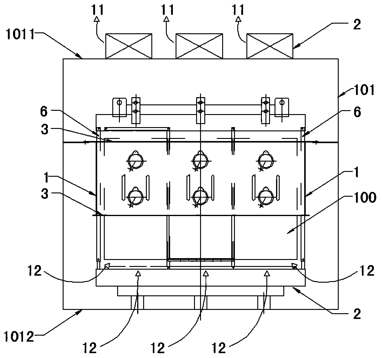
[0054] Please refer to image 3 , image 3 It is a structural schematic diagram of Embodiment 3 of the transformer cooling device of the present invention.
[0055] The air duct 1 encloses two-thirds of the transformer body 100 .
[0056] The air duct 1 surrounds the upper section of the transformer body 100 .
[0057] The following is a comparison of the data obtained through experiments in this example and the data described in the packaging method experiment in the background technology. The temperature rise data under the rated load loss of 3 hours, the cost of the heat sink (material and labor), and the packaging efficiency are listed respectively. Comparative data:
[0058]
[0059] Compared with the existing cooling device, the technical solution described in Embodiment 3 omits the technical feature of the upper air duct pipe, and the length of the air guide pipe 1 is only 2 / 3 of the original.
[0060] The experimental data show that, compared...
PUM
 Abstract
Description
Claims
Application Information
 - R&D Engineer
- R&D Manager
- IP Professional
- Industry Leading Data Capabilities
- Powerful AI technology
- Patent DNA Extraction
Browse by: Latest US Patents, China's latest patents, Technical Efficacy Thesaurus, Application Domain, Technology Topic, Popular Technical Reports.
© 2024 PatSnap. All rights reserved.Legal|Privacy policy|Modern Slavery Act Transparency Statement|Sitemap|About US| Contact US: help@patsnap.com