A position sensor for brushless DC motor

A brushed DC motor and sensor technology, applied in electromechanical devices, electrical components, etc., can solve the problems of large starting current fluctuation, increased volume and weight, long self-recovery time, etc., and achieve high reliability, light weight and low cost. Effect

Active Publication Date: 2016-03-30
HELLA SHANGHAI ELECTRONICS
View PDF5 Cites 0 Cited by
  • Summary
  • Abstract
  • Description
  • Claims
  • Application Information

AI Technical Summary

Problems solved by technology

Disadvantages: complex manufacturing process, high installation difficulty, increased volume and weight
Disadvantages: The success rate of starting is greatly affected by the change of external load, the starting current fluctuates greatly, the adaptability to instantaneous stall or speed change is poor, and the self-recovery time is long

Method used


Image

  • A position sensor for brushless DC motor
  • A position sensor for brushless DC motor
  • A position sensor for brushless DC motor

Examples


Embodiment Construction

[0025] The advantages of the present invention will be further described below in conjunction with specific embodiments and drawings.

[0026] In the preferred embodiments disclosed below, the permanent magnet rotor pole pair number M is 4, and the stator phase number N is 3 as an example.

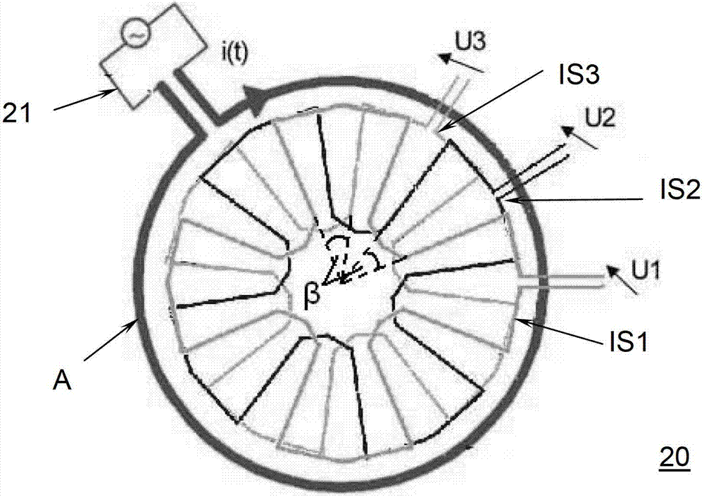
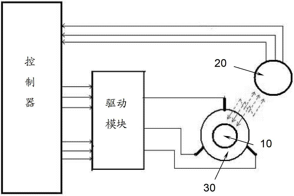
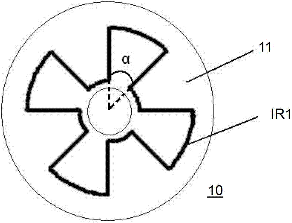
[0027] See figure 1 , figure 2 , Respectively show the rotor part 10 and the stator part 20 of the position sensor 100 provided by a preferred embodiment of the present invention.

[0028] The rotor part 10 is composed of a rotor printed circuit board 11 and a rotor induction coil IR1. The rotor printed circuit board 11 has a central hole 12 for fixed connection with the rotating shaft (not shown) of the brushless DC motor. The rotor induction coil IR1 is arranged around the central hole 12, and 4 protruding fan blades are evenly arranged in the circumferential direction. According to α=180 / N, the angle α of each protruding fan blade is 45 degrees, and the angle between two adjacent protruding...


PUM


Abstract

The invention provides a position sensor for a brushless direct current motor. The position sensor for the brushless direct current motor comprises a stator part and a rotor part which are adjacent to each other, wherein the stator part is fixedly arranged inside the brushless direct current motor and comprises an excitation source, an excitation coil, and M stator induction coils in concentric distribution, and M is the phase number of the stator; the rotor part comprises a rotor printed circuit board fixed with a rotating shaft of the brushless direct current motor, and a rotor induction coil is arranged on the rotor part; the M stator induction coils are coaxial with the rotor induction coil; N protruding fan blades are uniformly distributed circumferentially; N is the number of pole pairs of a permanent magnet rotor; the angle alpha of each protruding fan blade is 180 / N degrees; the spatial included angle beta between the M stator induction coils in the circumferential direction is 360 / (N*M) degrees.

Description

Technical field [0001] The invention relates to a position sensor, in particular to a position sensor for a brushless DC motor, which mainly solves the detection of the rotor position of the motor and realizes the commutation of the motor control circuit. Background technique [0002] With the continuous improvement of requirements for the life and energy efficiency of DC motors in various industries, brushless DC motors are now more and more widely used, and at the same time, higher requirements are put forward for the performance and cost of brushless DC motors. The position sensor technology of the brushless DC motor rotor is one of the core technologies in the entire technical chain. The use of different position sensor technologies also determines the performance of the motor to a certain extent. At present, the brushless DC motor position sensor technologies mainly include the following: [0003] 1. Photoelectric sensor technology. The photoelectric sensor is composed of a ...

Claims


Application Information

Patent Timeline
Patent Type & Authority Patents(China)
IPC IPC(8): H02K29/06
Inventor 毛文龙于伟潘滢亨宁·伊尔勒朱卫朱洁
Owner HELLA SHANGHAI ELECTRONICS
Why Eureka
Try Eureka