
A Self-optimized Control Method for Advance Commutation Angle of Electrically Excited Doubly Salient Motor

A technology of electric excitation doubly salient pole and control method, applied in the direction of single motor speed/torque control, sustainable manufacturing/processing, energy industry, etc., can solve the problem of increasing switching loss of power devices, difficult direct measurement, and complicated implementation process problem, to achieve the effect of simple implementation, reducing dead time and improving system efficiency

Active Publication Date: 2019-02-05
NANJING UNIV OF AERONAUTICS & ASTRONAUTICS
View PDF6 Cites 0 Cited by
  • Summary
  • Abstract
  • Description
  • Claims
  • Application Information

AI Technical Summary

Problems solved by technology

However, the selection of its control angle is related to multiple physical quantities such as motor parameters and loads, and the actual implementation process is complicated.
[0006] At present, many scholars increase the torque output by commutating the electric excitation doubly salient motor in advance and increasing the conduction state. However, the selection of the commutation angle is related to multiple physical quantities such as motor parameters and load conditions. In actual operation, each parameter changes and It is difficult to measure directly, which increases the difficulty of implementation; and the switching of multiple conduction states increases the switching loss of the power device, and the setting of the dead time reduces the efficiency of the doubly salient motor system

Method used


Image

  • A Self-optimized Control Method for Advance Commutation Angle of Electrically Excited Doubly Salient Motor
  • A Self-optimized Control Method for Advance Commutation Angle of Electrically Excited Doubly Salient Motor
  • A Self-optimized Control Method for Advance Commutation Angle of Electrically Excited Doubly Salient Motor

Examples


Embodiment Construction

[0030] The invention will be described in further detail below in conjunction with the accompanying drawings.

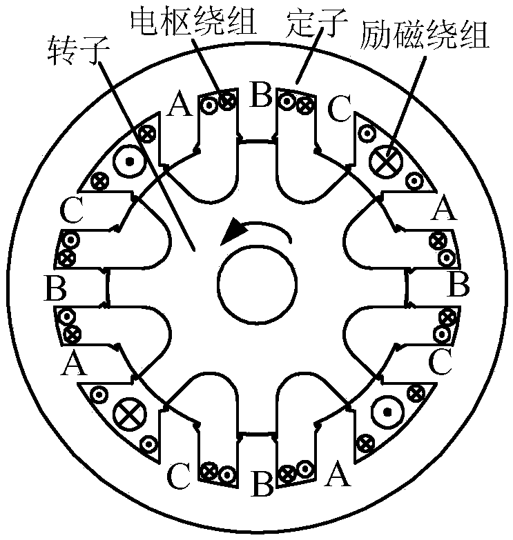
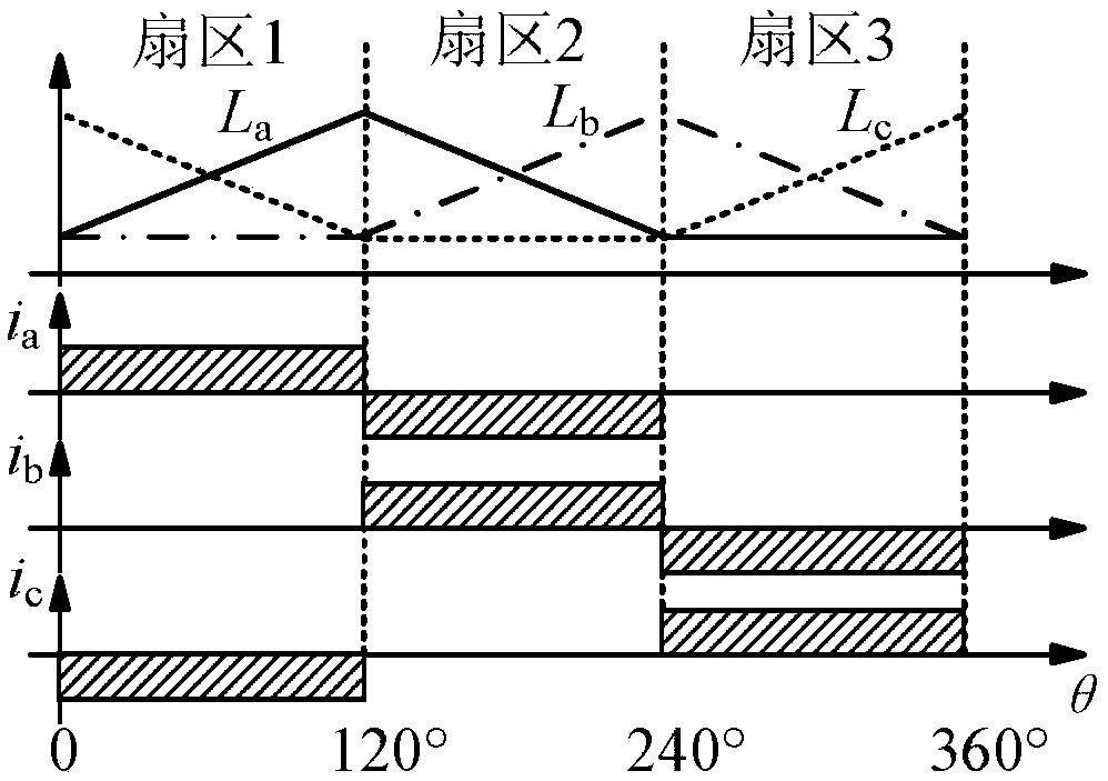
[0031] The electric excitation doubly salient motor and converter drive topology targeted by the present invention are as follows: figure 1 As shown, the electrically excited doubly salient motor is driven by a three-phase full-bridge converter, and the excitation part is driven by an asymmetrical half-bridge converter. The cross-section of an electrically excited doubly salient motor is figure 2 As shown, the stator and rotor are salient pole structures, and there are neither permanent magnets nor windings on the rotor. The "three-phase three-beat" power-on method often used in electrically excited double salient pole motors is as follows: image 3 As shown, one electrical angle cycle is divided into three conduction states. The system control block diagram of the present invention is as Figure 4 As shown, the system adopts the control mode of the speed outer ...


PUM


Abstract

The invention discloses a doubly salient electro-magnetic motor advance commutation angle self-optimization control method, and belongs to the technical field of motor control. The method realizes optimal advance angle commutation of a doubly salient electro-magnetic motor with obtaining of maximum output torque / current ratio under a state of steady state operation of a motor being as a target, an advance commutation angle being as an adjusting variable and a given current output by a rotation speed loop being as feedback. The method is characterized by initially setting an advance commutation angle [theta]Oini, and obtaining a current set point IR under the advance commutation angle; and comparing the current set point IR(k) and a current set point IR(k-1) obtained under a previous commutation angle to determine change direction of the advance commutation angle [theta]O, and so on, so that the system is allowed to operate in the steady state under the minimum current. The method can find the optimal advance commutation angle of the doubly salient electro-magnetic motor without motor and load parameters, improves torque output in the commutation phase, reduces torque ripples and improves system efficiency.

Description

technical field [0001] The invention relates to a method for self-optimizing control of the advance commutation angle of an electrically excited double salient motor, and belongs to the technical field of motor control. Background technique [0002] Electric excitation double salient pole motor is a new type of brushless DC motor, which has the advantages of simple and reliable structure, flexible control, good fault tolerance, and is suitable for harsh working conditions. It has broad application prospects in aviation, wind power and other fields. The basic "three-phase three-beat" conduction mode of the electrically excited double salient pole motor commutates at the point of maximum inductance, the current change is small, and the commutation lasts for a long time, which will cause a large torque drop. The larger the amplitude, the more obvious the torque drop. Early commutation can speed up the current change rate and reduce the commutation time. It is a feasible way to...

Claims


Application Information

Patent Timeline
Patent Type & Authority Patents(China)
IPC IPC(8): H02P6/06
CPCH02P6/06Y02P80/10
Inventor 周兴伟周波杨岚王开淼
Owner NANJING UNIV OF AERONAUTICS & ASTRONAUTICS
Learn More