Device for filtering and demodulating multipath signals

A filter demodulation and multi-channel signal technology, applied in the field of demodulator, can solve the problems that cannot meet the needs of multi-channel signal demodulation, and achieve the effect of strong practicability

Inactive Publication Date: 2014-03-26
成都威势科技有限公司
1 Cites 3 Cited by

AI-Extracted Technical Summary

Problems solved by technology

Existing demodulators can only demodulate single-channel filtered signals, which can...

Abstract

The invention discloses a device for filtering and demodulating multipath signals. The device comprises a capacitor C1, a capacitor C2, a capacitor C3, a capacitor C4, a capacitor C5, a resistor R1, a resistor R2, a resistor R3, a resistor R4, a resistor R5, a resistor R6, a resistor R7, a diode D1, a diode D2, an operation amplifier A1, an operation amplifier A2 and a triode T. The non-inverting input end of the capacitor C1, the capacitor C2 and the operation amplifier A1, the output end of the operation amplifier A1, the non-inverting output end of the diode D1, the diode D2 and the operation amplifier A2, the non-inverting input ends of the operation amplifier A2, the capacitor C4 and the capacitor C3 are sequentially serially connected to form a closed loop. The cathode common terminal of the diode D1 and the diode D2 is connected with the base set of the triode T, the resistor R7 and the capacitor C5. One end of the resistor R1 is connected to the common terminal of the capacitor C1 and the capacitor C2, and the other end thereof is connected with the inverting input end and the output end of the operation amplifier A1. By the arrangement, filtering and demodulating of the multipath signals in transmission can be achieved, and high practicality is achieved.

Application Domain

Multiple-port active networksElectromagnetic wave demodulation

Technology Topic

VIT signalsCapacitance +7

Image

  • Device for filtering and demodulating multipath signals

Examples

  • Experimental program(1)

Example Embodiment

[0013] Examples:
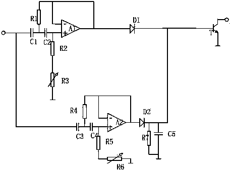
[0014] As shown in Figure 1, the present invention includes capacitor C1, capacitor C2, capacitor C3, capacitor C4, capacitor C5, resistor R1, resistor R2, resistor R3, resistor R4, resistor R5, resistor R6, resistor R7, diode D1, diode D2 , Operational amplifier A1, operational amplifier A2 and transistor T, resistor R7 and capacitor C5 are connected in parallel and resistor R7 and capacitor C5 are grounded, resistor R3 and resistor R6 are adjustable resistors, resistor R3 and resistor R6 are grounded; capacitor C1 The value is greater than the value of the capacitor C3, the value of the capacitor C2, the value of the capacitor C4 and the value of the capacitor C5 are equal. The capacitor C1, capacitor C2, the same direction input terminal of the operational amplifier A1, the output terminal of the operational amplifier A1, the diode D1, the diode D2, the output terminal of the operational amplifier A2, the same direction input terminal of the operational amplifier A2, and the capacitor C4 of this embodiment It is connected in series with the capacitor C3 to form a closed loop, and the common terminal of the capacitor C1 and the capacitor C3 is connected to the input signal. The common terminals of the cathodes of the diode D1 and the diode D2 in this embodiment are simultaneously connected to the base set of the transistor T, the resistor R7 and the capacitor C5. One end of the resistor R1 in this embodiment is connected to the common end of the capacitor C1 and the capacitor C2, and the other end is simultaneously connected to the inverting input and output ends of the operational amplifier A1; one end of the resistor R4 is connected to the common end of the capacitor C3 and the capacitor C4, and the other end is simultaneously connected The reverse input and output ends of the operational amplifier A2; the two ends of the resistor R2 are respectively connected to the output end of the capacitor C2 and the resistor R3; the two ends of the resistor R5 are respectively connected to the output end of the capacitor C4 and the resistor R6. The collector of the triode T in this embodiment is connected to the signal output terminal, and the emitter is grounded.
[0015] The input signal passes through two different filters at the same time. The first filter includes capacitor C1, capacitor C2, resistor R1, resistor R2, resistor R3, and operational amplifier A1. The second filter includes capacitor C3, capacitor C4, and resistor R4. , Resistor R5, resistor R6 and operational amplifier A2. When the signal filtered by the first filter passes through the transistor, the transistor is cut off and the output is open; when the signal filtered by the second filter passes through the transistor, the transistor is saturated and the output is short-circuited. When adjusting the circuit, input the frequency band of the first filter and the frequency band of the second filter into the circuit separately, adjust the adjustable resistance to maximize the output of the two filters, and realize the filtering and demodulation of the transmitted multiple signals at the same time. More practical.

PUM

no PUM

Description & Claims & Application Information

We can also present the details of the Description, Claims and Application information to help users get a comprehensive understanding of the technical details of the patent, such as background art, summary of invention, brief description of drawings, description of embodiments, and other original content. On the other hand, users can also determine the specific scope of protection of the technology through the list of claims; as well as understand the changes in the life cycle of the technology with the presentation of the patent timeline. Login to view more.

Similar technology patents

Remote iris tracking and acquiring method based on microphone array

ActiveCN107346661Aimprove accuracyPractical
Owner:伊沃人工智能技术(江苏)有限公司

Wallboard installation robot

Owner:GUANGDONG BOZHILIN ROBOT CO LTD

Classification and recommendation of technical efficacy words

  • Practical

User behavior self-learning air conditioning system and control method thereof

ActiveCN105318499AConvenience and good experiencePractical
Owner:GD MIDEA AIR-CONDITIONING EQUIP CO LTD +1

Optimization method for spray gun track of spraying robot on irregular polyhedron

ActiveCN102500498APracticalImprove work efficiency and product quality
Owner:JIANGSU NEWBLUE INTELLIGENT EQUIP CO LTD

Intelligent grid comprehensive evaluating system based on analytic hierarchy process and fuzzy comprehensive evaluation

InactiveCN102663508ADemonstrate economic and social benefitsPractical
Owner:NORTHEAST POWER SCI RES INSTITUTION +2
Why Eureka
Try Eureka