Time synchronization method and device of optical transport network asynchronous network

An asynchronous network and optical transport network technology, applied in the field of communication, can solve problems such as incompatibility of OSC, inability to realize time through transformation, and inability to support equipment hardware architecture, so as to achieve the effect of realizing time

Active Publication Date: 2014-03-26
ZTE CORP
View PDF4 Cites 13 Cited by
  • Summary
  • Abstract
  • Description
  • Claims
  • Application Information

AI Technical Summary

Problems solved by technology

[0007] Among them, the above-mentioned first method will cause the time synchronization performance to drop sharply due to the functions of mapping / demapping, multiplexing / demultiplexing, and switching in the OTN equipment; the second method requires the OSC-terminated 1588 The message is re-initiated on another OSC channel, which may not be supported by the existing hardware architecture, and the OSC of each manufacturer may not be compatible; the third method is that since OTN is an asynchronous system, the sending frequency of each port may be free oscillation The system clock (regeneration service) may also restore the clock for the service (transparent service), and the backplane design of the OTN equipment on the existing network may not support the synchronization of time stamps between service boards, so it may Unable to achieve time synchronization with retrofit
[0008] To sum up, if the OTN equipment system architecture of the existing network cannot be changed, the maximum clock frequency deviation of each site is 20ppm (one millionth of a second). In this case, precise time synchronization cannot be achieved

Method used


Image

  • Time synchronization method and device of optical transport network asynchronous network
  • Time synchronization method and device of optical transport network asynchronous network
  • Time synchronization method and device of optical transport network asynchronous network

Examples


Embodiment Construction

[0043] In order to facilitate the description of the present invention, the implementation of the technical solutions of the present invention will be further described in detail below in conjunction with the accompanying drawings and specific embodiments. It should be noted that, in the case of no conflict, the embodiments in the present application and the features in the embodiments can be combined arbitrarily with each other.

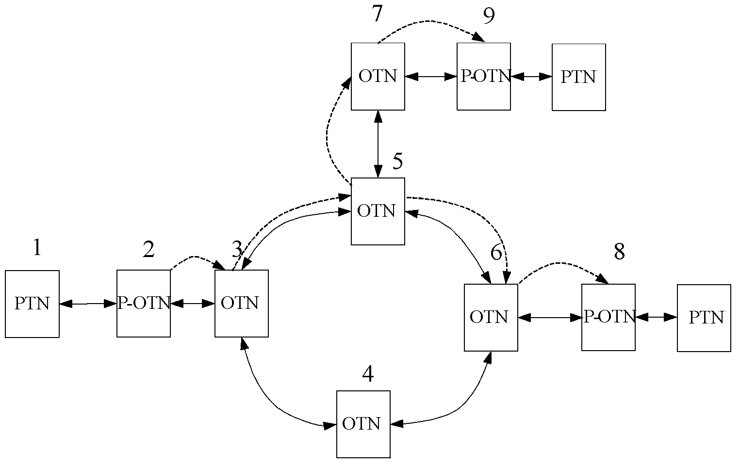
[0044] like figure 1 As shown, using PTN, P-OTN (Packet Optical Transport Network) and OTN equipment joint networking, wherein the P-OTN equipment has a synchronous EEC (Ethernet Equipment Clock, Ethernet equipment clock) clock synchronization function, figure 1 Sites 3-7 in the figure are existing OTN networks, and the clocks of each OTN site are in free oscillation. The solid line in the figure represents the existing service configuration, the dotted line represents the time synchronization path, and the interface is OTUk (k=1, 2, 3 or 4). Assu...


PUM


Abstract

The invention discloses a time synchronization method and a time synchronization device of an optical transport network asynchronous network. When a site in an optical transport network receives a time message transmitted by other sites, a first line card in the site recovers clock frequencies of one or a plurality of clock optical path data units(ODUm), wherein m is positive integers which are less than or equal to k, k is an optical path data unit order, and k is equal to 1, 2, 3 and 4, the service of the first line card uses a local clock to be converted to a data frame format of a back plate, the clock ODUm is sent to a second line card in the site through a cross board; the second line card uses the local clock to receive data frames of the back plate and restore the clock frequency of the clock ODUm, and the local clock or a service restoring clock of an optical path transmitting unit (OTUn) optical port is used to send the whole OTUn, wherein n is the order of the optical path transmitting unit. By adopting the time synchronization method and the time synchronization device of the optical transport network asynchronous network disclosed by the invention, the high-precision time synchronization can be supported under the condition that the present optical transport network OTN is asynchronous.

Description

technical field [0001] The invention relates to a time synchronization technology in the communication field, in particular to a time synchronization method and device for an asynchronous network of an optical transmission network. Background technique [0002] With the development of packet services, PTN (Packet Transport Network, Packet Transport Network) is rising day by day. It is not only suitable for multi-service bearer, but also can provide clock synchronization (synchronous Ethernet) and 1588 time synchronization functions, which can be very good Supports mobile backhaul features. However, if the services converged by the PTN equipment are transmitted through the existing OTN (Optical Transport Network, Optical Transport Network), it is necessary to consider the bearer mode of the OTN for time synchronization. [0003] At present, OTN mainly supports the time transfer of PTN in the following three ways: [0004] 1. The client signal transmits the 1588 protocol on ...

Claims


Application Information

Patent Timeline
Patent Type & Authority Applications(China)
IPC IPC(8): H04L7/00H04Q11/00
Inventor 曹志刚
Owner ZTE CORP
Why Eureka
Try Eureka