
Linear led driving circuit using score divider for adjusting voltage

A technology for LED driving and voltage regulation, which is applied in the direction of electric lamp circuit layout, electric light source, lighting device, etc., and can solve the problem of storage pressure in terms of cost

Inactive Publication Date: 2014-03-26
LUXUL TECH
View PDF7 Cites 18 Cited by
  • Summary
  • Abstract
  • Description
  • Claims
  • Application Information

AI Technical Summary

Problems solved by technology

[0008] However, since the allowable error range of the voltage of the aforementioned AC power supply AC / IN is 99 volts to 122 volts; therefore, manufacturers of linear LED driving circuits must design different linear LED driving circuits for different voltage ranges, causing manufacturers cost and storage pressure; therefore, it is necessary to propose a better solution for the above situation

Method used


Image

  • Linear led driving circuit using score divider for adjusting voltage
  • Linear led driving circuit using score divider for adjusting voltage
  • Linear led driving circuit using score divider for adjusting voltage

Examples


no. 1 example

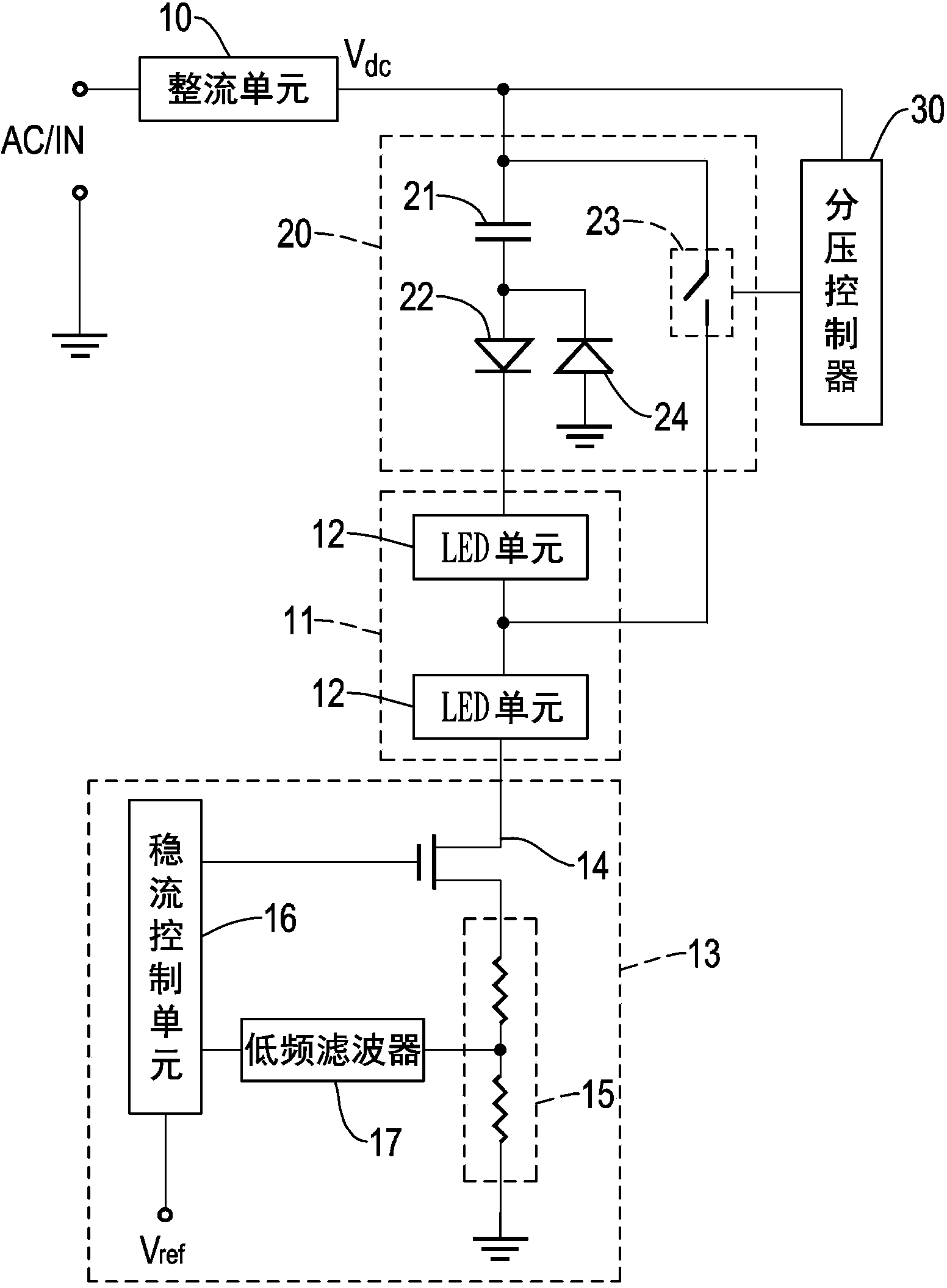
[0048] Please refer to figure 1 As shown, the first embodiment of the linear LED driving circuit using a fractional voltage divider to adjust the voltage of the present invention includes:

[0049] A rectification unit 10, connected to an AC power supply AC / IN, and converting the above-mentioned AC power supply AC / IN into a pulsating DC power supply; in this embodiment, the rectification unit 10 is a full-wave rectifier;

[0050]An LED module 11 is connected in series with the rectifier unit 10 and includes a plurality of LED units 12 connected in series; in this embodiment, the above-mentioned LED module 11 includes two LED units 12, and each LED unit 12 includes multiple LED units light source;

[0051] A constant current controller 13 is connected in series between the LED module 11 and a ground terminal to form a power circuit; wherein the constant current controller 13 makes the current flowing through the power circuit fixed at a certain value; in this embodiment The ...

no. 5 example

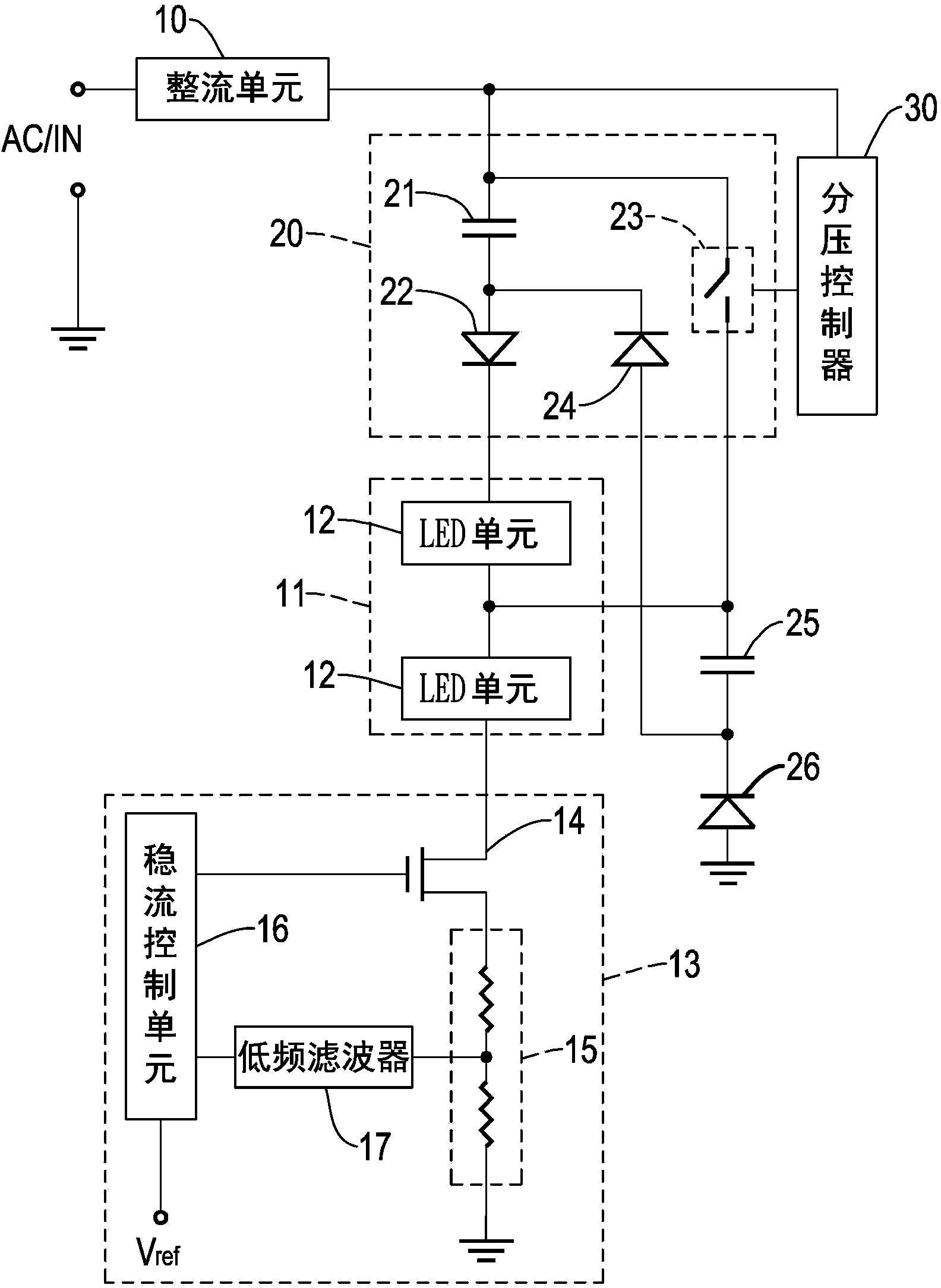
[0071] Please refer to Figure 5 As shown, the fifth embodiment of the linear LED driving circuit using a fractional voltage divider to adjust the voltage of the present invention includes:

[0072] A rectification unit 10 is connected to an AC power supply AC / IN, and converts the above-mentioned AC power supply AC / IN into a pulsating DC power supply; in this embodiment, the rectification unit 10 is a full-wave rectifier

[0073] An LED module 11, connected in series with the rectifier unit 10, and includes a plurality of LED units 12; in this embodiment, the LED module 11 includes two LED units 12, and each LED unit 12 includes multiple LED light sources;

[0074] A constant current controller 13 is connected in series between the LED module 11 and a ground terminal to form a power circuit; wherein the constant current controller 13 makes the current flowing through the power circuit fixed at a certain value; in this embodiment The constant current controller 13 includes a v...


PUM


Abstract

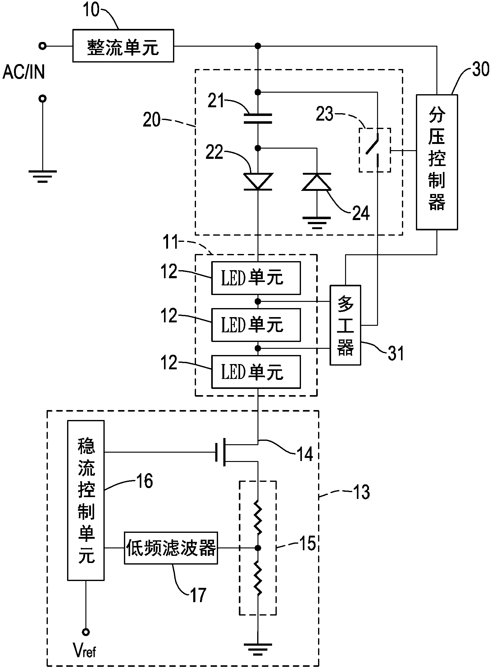
The invention provides a linear LED driving circuit used a score divider for adjusting voltage. The circuit includes a power circuit composed of a rectifying unit, an LED module and a current controller, and a serial-parallel score divider connected to the LED module and a voltage dividing controller connected to the serial-parallel score divider. The serial-parallel score divider includes a voltage dividing capacitor connected to the LED module in series. When discharging, the voltage dividing capacitor is connected between at least one LED unit and a grounding terminal of the LED module. Since voltage across the voltage dividing capacitor is equal to that across two ends of the LED unit, voltage value of the voltage dividing capacitor can be decided by controlling quantity of the LED units connected to the current controller in series. Input voltage can be reduced to an arbitrary score voltage dividing value suitable for LED quantity, so that the circuit can be suitable for different voltages.

Description

technical field [0001] The invention relates to a linear LED driving circuit, in particular to a linear LED driving circuit using a fractional voltage divider to regulate voltage. Background technique [0002] Alternating current is the most common way of power transmission and distribution on the market at present. The reason is that it is far more efficient to transmit power through AC than through DC. At present, the standard voltage of the AC power sent to each household by the power company is 110 Volts or 220 volts, but in fact the voltage of the AC power received by the user is not as ideal as the above, but there will be a slight error range; generally speaking, the above error range roughly falls within the range of +-10%; For example, if the effective value of the voltage of the AC power is 110 volts, the voltage of the AC power of 99 volts to 122 volts is within the allowable error range. [0003] Light Emitting Diode (LED; Light Emitting Diode) is a common light...

Claims


Application Information

Patent Timeline
IPC IPC(8): H05B37/02
Inventor 潘政宏喻鹏飞
Owner LUXUL TECH
Learn More