Machine box sliding rail

A sliding rail and chassis technology, applied in the direction of rack/frame structure, etc., can solve the problems of poor bearing capacity of the sliding rail and the vibration of the chassis, and achieve the effect of enhancing stability and eliminating the deformation of the sliding rail of the chassis.

Active Publication Date: 2014-03-26
HUBEI SANJIANG AEROSPACE HONGFENG CONTROL
View PDF3 Cites 2 Cited by
  • Summary
  • Abstract
  • Description
  • Claims
  • Application Information

AI Technical Summary

Problems solved by technology

[0003] Aiming at the above defects or improvement needs of the prior art, the present invention provides a chassis slide rail, the purpose of which is to effectively enhance the overall stability of the slide rail, eliminate the deformation of the chassis slide rail caused by the vibration of the chassis during transportation, and thus solve the current problem. In the existing technology, the bearing capacity of the slide rail is poor, and there are technical problems of vibration during the transportation of the chassis

Method used


Image

  • Machine box sliding rail
  • Machine box sliding rail

Examples


Embodiment Construction

[0011] In order to make the object, technical solution and advantages of the present invention clearer, the present invention will be further described in detail below in conjunction with the accompanying drawings and embodiments. It should be understood that the specific embodiments described here are only used to explain the present invention, not to limit the present invention. In addition, the technical features involved in the various embodiments of the present invention described below can be combined with each other as long as they do not constitute a conflict with each other.

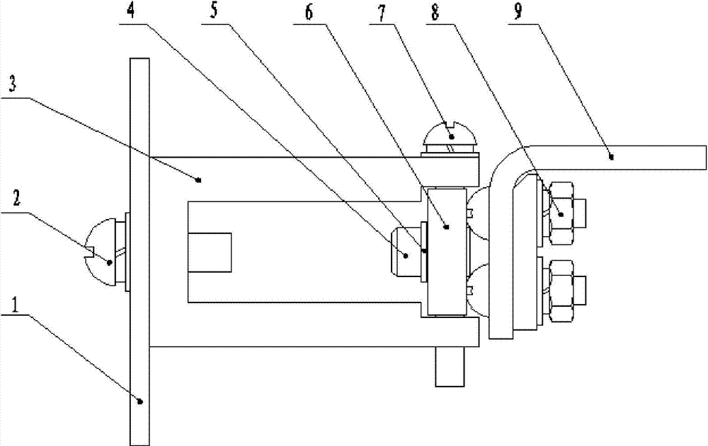
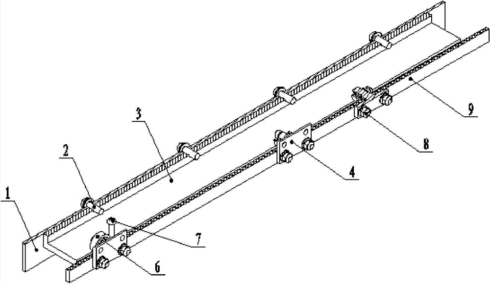
[0012] The invention relates to a cabinet slide rail, which is used for installing heavy parts and can meet the requirement of sliding.

[0013] In view of the above, it is necessary to propose a slide rail, which can effectively enhance the overall stability of the slide rail, thereby eliminating the deformation of the chassis slide rail caused by the vibration of the chassis during transportat...


PUM


Abstract

The invention discloses a machine box sliding rail. The machine box sliding rail comprises a first sliding rail body and a plurality of sets of second sliding rail bodies, wherein the first sliding rail body is installed on a machine box supporting frame through first fastening pieces and provided with a limiting screw, and the second sliding rail bodies can slide inside the first sliding rail body. The second sliding rail bodies are installed on the side face of a supporting plate through second fastening pieces. Each second sliding rail body is composed of a shaft, a bearing and a shaft check ring. The first sliding rail body is of a U-shaped structure, and is used for providing sliding ways for the second sliding rail bodies and limiting the transverse line displacement of the second sliding rail bodies. The number of the sets of the second sliding rail bodies is at least three. One end of each shaft is in a square shape and is used for being connected with an installing supporting plate, and the other end of each shaft is in a cylindrical shape and is used for installing the corresponding bearing and providing limiting for the corresponding bearing. The first sliding rail body is made of steel materials, the requirement for the rigidity of the sliding rail is met, and the appearance of the first sliding rail body can be changed according to the installing position of a machine box. The limiting screw is installed on the first sliding rail body to prevent the installing supporting plate from sliding out of the machine box during the sliding process. The integral stability of the sliding rail can be effectively enhanced, and the deformation, caused by vibration when the machine box is transported, of the machine box sliding rail is eliminated.

Description

technical field [0001] The invention belongs to the field of cabinets, and more specifically relates to a cabinet slide rail. Background technique [0002] Slide rails are widely used on devices that can carry objects to make two objects slide relative to each other. At first, they were mostly used in furniture such as drawers, computer keyboard trays, etc., and later they were used in electronic devices such as servers. This type of slide rail is processed by bending a thin plate, resulting in insufficient rigidity and poor load-carrying capacity. During the transportation of the chassis, there is vibration, which causes the chassis slide rail to deform and the slide rail cannot be pulled out. Contents of the invention [0003] Aiming at the above defects or improvement needs of the prior art, the present invention provides a chassis slide rail, the purpose of which is to effectively enhance the overall stability of the slide rail, eliminate the deformation of the chassis...

Claims


Application Information

Patent Timeline
Patent Type & Authority Applications(China)
IPC IPC(8): H05K7/18
Inventor 王红平杨双俊陈公仆
Owner HUBEI SANJIANG AEROSPACE HONGFENG CONTROL
Why Eureka
Try Eureka