
External fixation clamping system using a trigger mechanism and stored spring energy

A fixed clamping and energy storage technology, used in external fixators, fixators, etc.

Active Publication Date: 2014-03-26
ZIMMER INC
View PDF5 Cites 5 Cited by
  • Summary
  • Abstract
  • Description
  • Claims
  • Application Information

AI Technical Summary

Problems solved by technology

It's at least troublesome

Method used


Image

  • External fixation clamping system using a trigger mechanism and stored spring energy
  • External fixation clamping system using a trigger mechanism and stored spring energy
  • External fixation clamping system using a trigger mechanism and stored spring energy

Examples


Embodiment Construction

[0034] In order to promote an understanding of the principles of the invention, reference will now be made to the embodiments or examples illustrated in the drawings and specific terminology will be used to describe these embodiments or examples. However, it will be understood that the scope of the present invention is not intended to be limited thereby. Any changes and further modifications in the described embodiments, and any further application of the principles of the invention described herein will be appreciated by those skilled in the art to which the invention pertains.

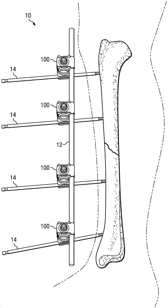
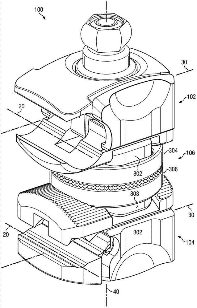
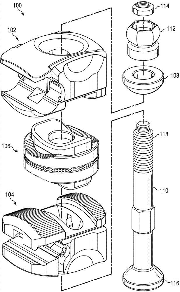
[0035] The present application relates to an external fixation system with a clamping assembly applying a system of the trigger and click type, which is performed before the stabilizing element is inserted into the clamp than after the stabilizing element is inserted The clamp then stores a higher level of spring energy.

[0036] In one aspect, the present application relates to an external fixation...


PUM


Abstract

An external fixation clamp for receiving a fixation element includes an inner jaw and an outer jaw movable between an open position that permits the fixation element to be placed between the inner and outer jaws and a closed position that restricts removal of the fixation element from between the inner and outer jaws. A latch assembly may cooperate with the inner and outer jaws to secure the jaws in a closed position. The latch assembly may comprise a latch and a latch biasing member. The latch may be configured to translate linearly relative to one of the inner and outer jaws, and the latch biasing member may have a first higher level of stored energy when the inner and outer jaws are in the open position and a second lower level of stored energy when the inner and outer jaws are in the closed position.

Description

technical field [0001] The present application relates to an externally fixed clamping system utilizing a trigger mechanism, and more particularly, the present application relates to an externally fixed clamping system with spring stored energy. Background technique [0002] External fixation systems are used to stabilize broken bones or to hold bones in place after orthopedic surgery. The external fixation system typically consists of structural components held together by multiple jigs, all of which will be assembled by the surgeon during surgery. The clamp is placed on the bone screw and attached to the rod, forming a framework for holding the bone in a specific relationship. Generally, the external fixation frame is assembled into the configuration desired by the surgeon, then the cracks are reduced and the clamps are tensioned. Some conventional jigs must be partially tensioned to temporarily lock the nail or rod in the jig. [0003] In one known externally fixed gri...

Claims


Application Information

Patent Timeline
IPC IPC(8): A61B17/64
CPCA61B17/6466A61B17/6475
Inventor M·W·马拉尼
Owner ZIMMER INC
Learn More