
Transverse magnetic field voltage isolator

a transverse magnetic field and voltage isolator technology, applied in the field of voltage isolation, can solve the problems of impracticality, ineffective technique in reducing the breakdown threshold voltage, and problematic avalanche ionization, so as to reduce the probability of avalanche ionization, reduce the energy of collisions, and reduce the effect of electron potential energy

Inactive Publication Date: 2009-11-03
KLA TENCOR TECH CORP
View PDF25 Cites 0 Cited by
  • Summary
  • Abstract
  • Description
  • Claims
  • Application Information

AI Technical Summary

Benefits of technology

"The present invention is about techniques for reducing the likelihood of avalanche ionization in low-pressure applications. The invention involves creating a transverse magnetic field across a gas passageway to reduce the potential energy of charged particles passing through the passageway. This reduces the likelihood of avalanche ionization and allows for the use of low-flow rate gas transfer. The invention also includes a vacuum chamber and a vacuum pump connected to the gas passageways, which maintains a vacuum within the passageways. The method involves guiding gas along at least two pathways and directing a magnetic field through each pathway to reduce the potential energy of charged particles. Overall, the invention provides a safer and more efficient way to transfer gas in low-pressure environments."

Problems solved by technology

Avalanche ionization is problematic, for example, in low-pressure applications (e.g., less than 10 Torr) in which a component that is maintained at a high voltage is separated from another component, which is maintained at ground potential, by a gas-filled passageway.
However, these techniques have certain drawbacks that leave the industry wanting for a more superior method.
This technique is impractical, however, because the necessary distances are typically infeasible in light of physical space limitations.
Unfortunately, this technique is simply not very effective in reducing the breakdown threshold voltage.
The dielectric material reduces the potential of the electrons, however, it also significantly impedes the flow of gas.
In the case where the bias is of an A / C nature, a faraday cup has been used with limited success.

Method used


Image

  • Transverse magnetic field voltage isolator
  • Transverse magnetic field voltage isolator
  • Transverse magnetic field voltage isolator

Examples


Embodiment Construction

[0021]The present invention will now be described in detail with reference to a few preferred embodiments thereof as illustrated in the accompanying drawings. In the following description, numerous specific details are set forth in order to provide a thorough understanding of the present invention. It will be apparent, however, to one skilled in the art, that the present invention may be practiced without some or all of these specific details. In other instances, well known operations have not been described in detail so not to unnecessarily obscure the present invention.

[0022]The present invention pertains to techniques for increasing the breakdown threshold voltage at which avalanche ionization can occur within low-pressure environments. One specific implementation of the invention involves providing high voltage isolation between a vacuum chamber and a vacuum pump in pressure range of approximately 1 mill-Torr-1 Torr with little or no current load on the voltage source and withou...


PUM

PropertyMeasurementUnit
pressureaaaaaaaaaa
voltageaaaaaaaaaa
voltageaaaaaaaaaa

Abstract

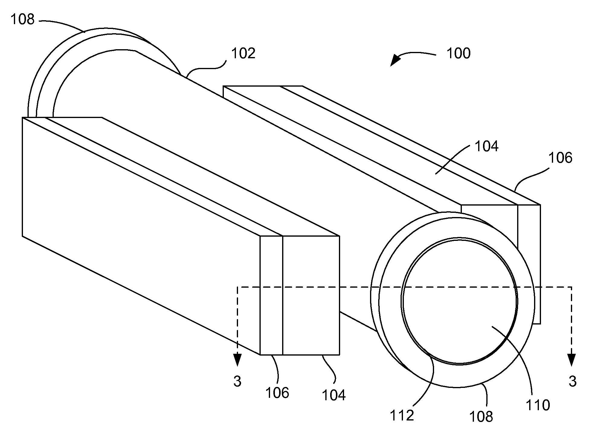
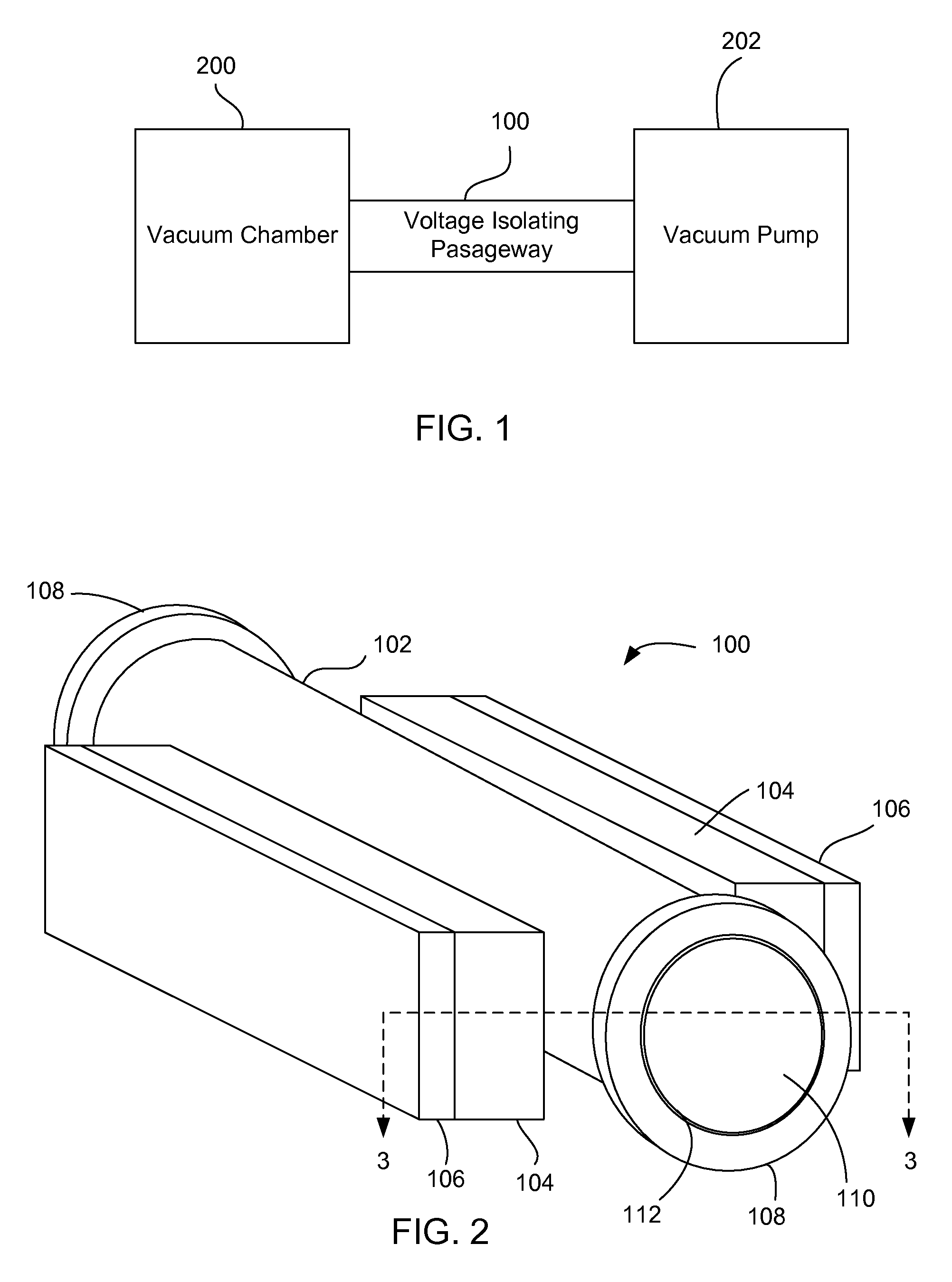
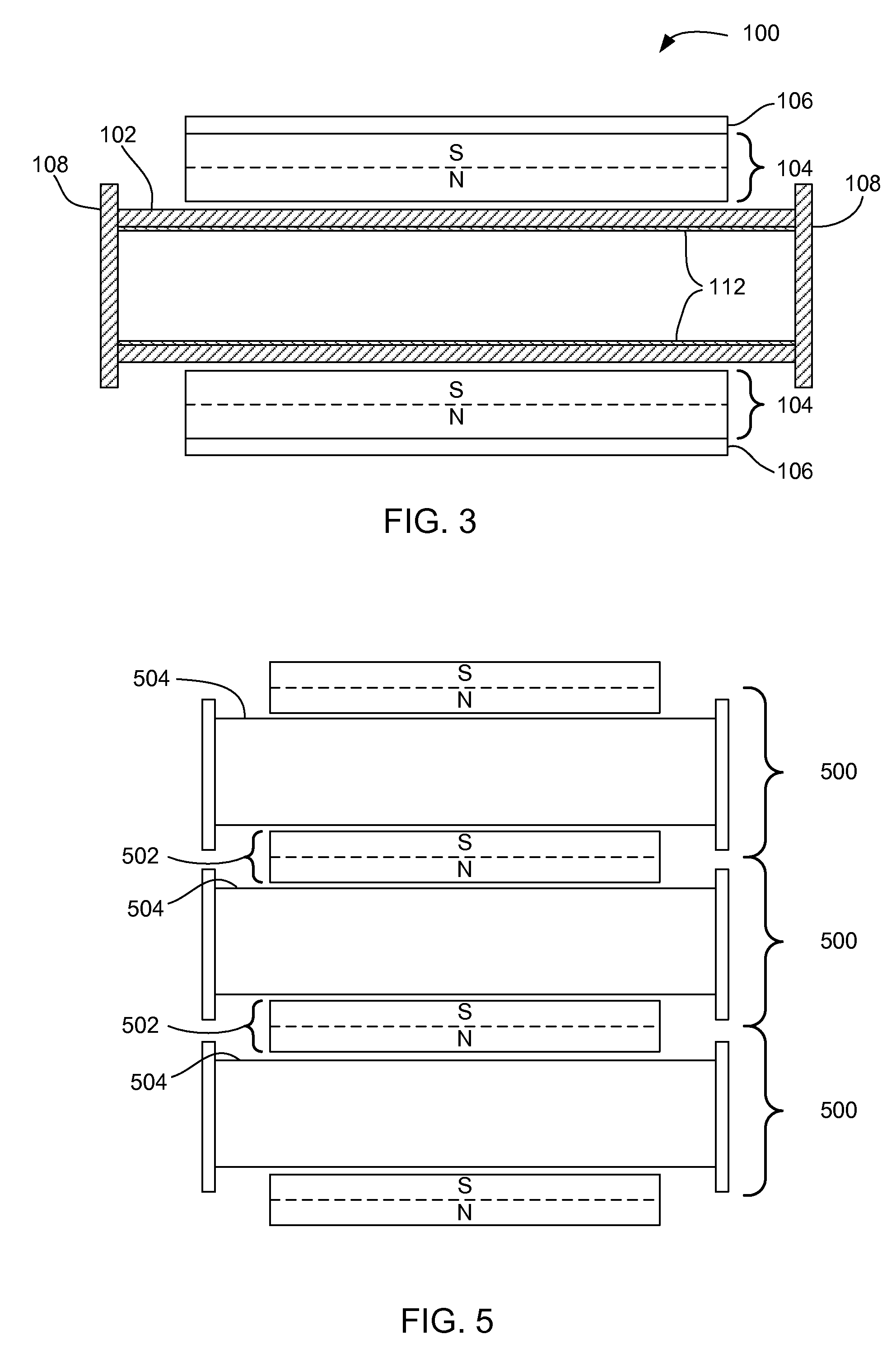
A voltage-isolating passageway for providing high voltage isolation between a component maintained at high DC voltage and a component maintained at a substantially lower voltage is described. The voltage-isolating passageway incorporates a transverse magnetic field across its passageway, which reduces the potential energy of charged particles (e.g., electrons) passing through the passageway. The voltage-isolating passageway includes a passageway and at least two magnets. The passageway has two openings and the two magnets are positioned along opposite and exterior surfaces of the passageway wherein the first and second magnets impose a magnetic field in a transverse direction with respect to a lengthwise axis of the passageway. In one embodiment, each of the passageways have small diameters and transfer gases at small flow rates. A support structure secures the passageways and magnets in position relative to each other and a magnetic shield encases the components to prevent the magnetic field from affecting external components.

Description

CROSS-REFERENCE TO RELATED APPLICATIONS[0001]This application is a division of prior U.S. patent application Ser. No. 10 / 882,663, filed Jun. 30, 2004, entitled “Transverse Magnetic Field Voltage Isolator,” which is incorporated herein by reference in its entirety for all purposes. This application is related to U.S. Pat. No. 6,746,566, entitled “Transverse Magnetic Field Voltage Isolator,” U.S. Pat. No. 7,321,125, entitled “Transverse Magnetic Field Voltage Isolator,” and to U.S. Pat. No. 6,710,354, entitled “Scanning Electron Microscope Architecture and Related Material Handling System,” the contents of each of which are hereby incorporated by reference.FIELD OF THE INVENTION[0002]The present invention relates generally to voltage isolation, and more specifically to magnetic voltage isolation techniques.BACKGROUND OF THE INVENTION[0003]Avalanche ionization is a physical phenomenon that significantly decreases the operating voltage range of various low-pressure systems. Avalanche io...

Claims


Application Information

Patent Timeline
Patent Type & Authority Patents(United States)
IPC IPC(8): H01J37/18H01F7/02
CPCC09K11/773H01J2237/26H01J2237/16H01J2237/038
Inventor GUBBENS, ALEXANDER JOZEFMACDONALD, NILES KENNETHNASSER-GHODSI, MEHRANGARCIA, RUDY FLORESMASNAGHETTI, DOUG KEITH
Owner KLA TENCOR TECH CORP
Learn More