Component supply apparatus

一种供给装置、部件的技术,应用在程序控制机械手、程序控制、仪器等方向,能够解决电力消耗大、需要机器手切换时间机器手宽阔场所、最终码放失败等问题,达到避免周期时间的延长、减小临时放置场所、缩短设计时间的效果

Active Publication Date: 2014-03-26
MITSUBISHI ELECTRIC CORP
View PDF8 Cites 15 Cited by
  • Summary
  • Abstract
  • Description
  • Claims
  • Application Information

AI Technical Summary

Problems solved by technology

Therefore, there are parts that do not have the function of a suction pad, such as parts that cannot handle planar shapes, parts with complex shapes, parts with uneven surfaces, parts with many small holes, and parts with thin shapes. Problems with components on suction cups
[0012] In addition, when the suction cup cannot be used, it is also conceivable to use a blower to perform suction, but in this case, there are problems of large noise and large power consumption.
[0013] In addition, in either case of Patent Documents 1 and 2, a dedicated robot designed for each component is used in order to absorb large errors that may lead to final stacking failure. Therefore, the same robot cannot be used. Stacking multiple parts requires the same number of robots as the number of parts, which requires time for switching between robots and a wide space for temporary placement of robots.
[0014] In addition, it is necessary to redesign the robot for each part, so when the model to be produced is changed, there is a problem that costs for remaking the robot (design, production, and adjustment costs) are required

Method used


Image

  • Component supply apparatus
  • Component supply apparatus
  • Component supply apparatus

Examples


Embodiment approach 1

[0044] Below, refer to Figure 1 to Figure 5 , Embodiment 1 of the present invention will be described.

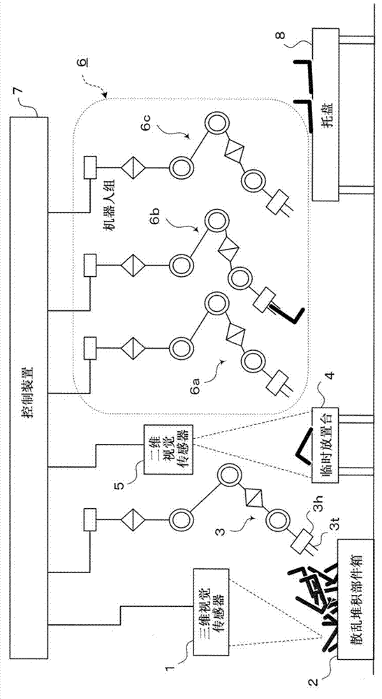
[0045] figure 1 It is a side view schematically showing the overall structure of the parts supply device according to Embodiment 1 of the present invention, and shows the stacking and supply of scattered parts using a plurality of (here, four) robots 3 , 6 a , 6 b , and 6 c Structure.

[0046] exist figure 1 Among them, the parts supply device has: a three-dimensional vision sensor 1; a scattered parts box 2, which accommodates a plurality of parts (for example, L-shaped parts); a first robot 3 (hereinafter referred to as "robot 3"), which is close to the scattered Component boxes 2 are piled up and arranged; a temporary storage platform 4 for components; a two-dimensional vision sensor 5 that photographs the temporary storage platform 4; a robot group 6 (second robot) consisting of robots 6a to 6c; a control device 7, Based on the detection results of the three-dimens...

Embodiment approach 2

[0163] In addition, in the above-mentioned Embodiment 1 ( Figure 1 to Figure 5 ), there is no particular description, but in order to optimize the success rate of grabbing the parts in the scattered parts box 2 during the action of the robot 3 associated with the three-dimensional vision sensor 1 and the control device 7, it is also possible to install A parameter optimization unit for selecting optimal parameters.

[0164] Below, refer to Figure 1 to Figure 4 , Embodiment 2 of the present invention in which a parameter optimization means is provided will be described.

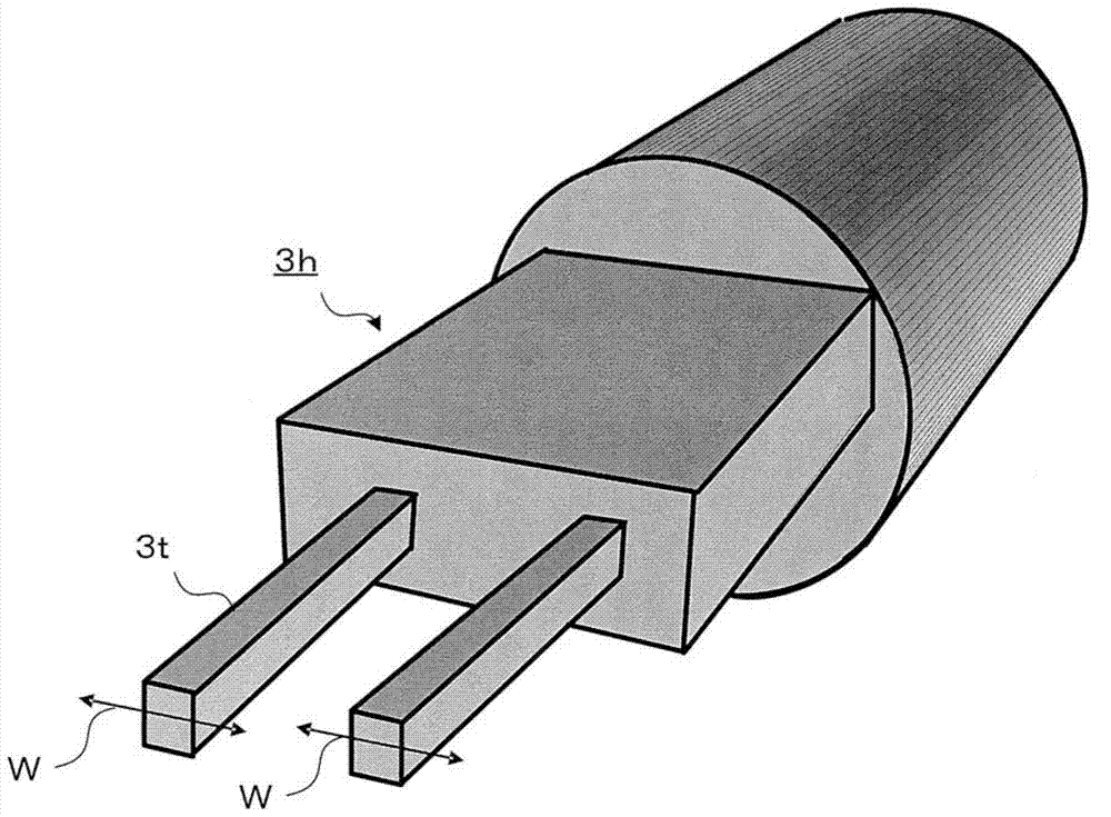
[0165] The operation of the robot 3 includes an operation of closing the claw 3t and grasping it after the robot 3 is operated so that the position and posture of the ear of the part coincide with the position and posture of the claw 3t of the robot hand 3h of the robot 3. part.

[0166] At this time, it is necessary to adjust the value of the width W, the value of the posture, and various numerical param...

Embodiment approach 3

[0193] In addition, in the above-mentioned first and second embodiments, the functions and features of each part are not collectively described, but the stacking effect of the random stacking parts according to the present invention can be realized by the following first to fifth features (functions).

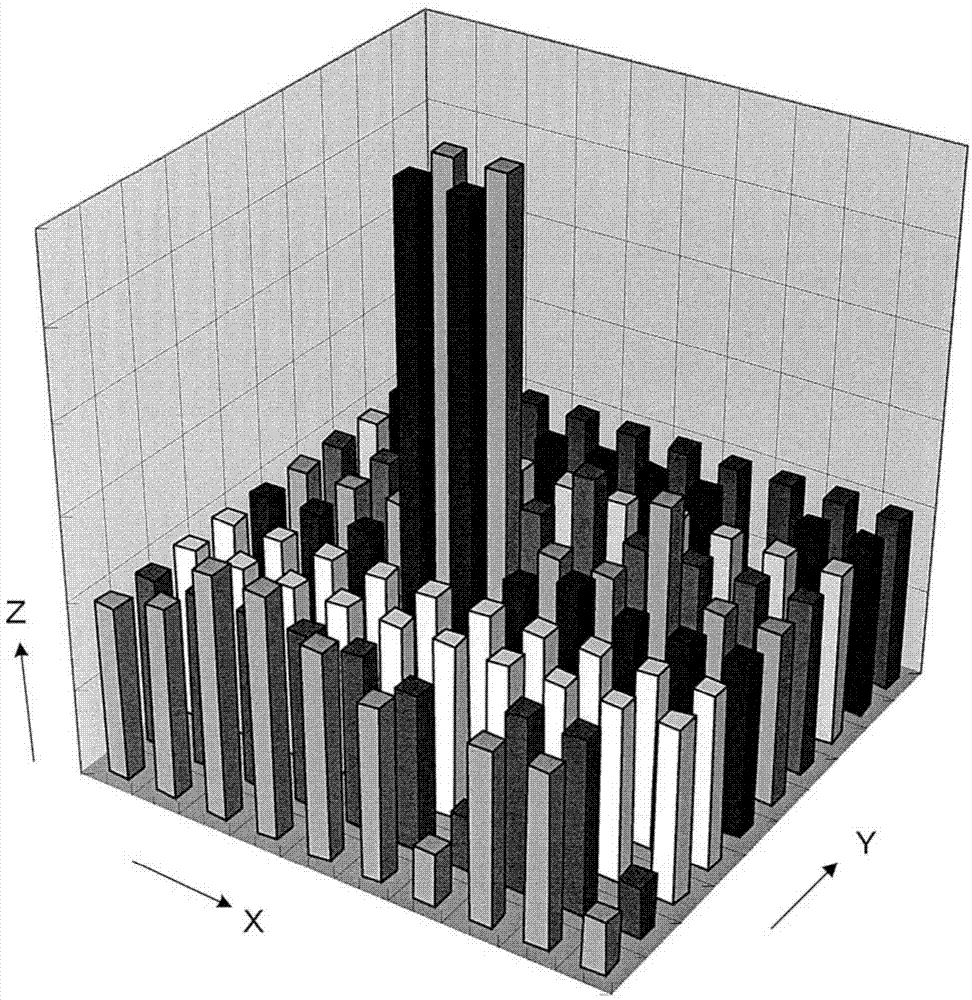
[0194] First, the first feature is that it has a distance image measuring unit composed of the three-dimensional vision sensor 1 and the control device 7 .

[0195] For example, in an existing device, a position and posture for holding a component is set in advance corresponding to the type of the component. In contrast, in the present invention, instead of setting a position and posture, it has the following function: When performing a grasping action, the three-dimensional vision sensor 1 performs measurement, and flexibly changes the grasping position and subsequent actions corresponding to the obtained measurement data.

[0196] In addition, in the present invention, the th...


PUM


Abstract

[Purpose] To provide a component supply apparatus for arranging variously shaped components supplied in bulk at high speed by using general-purpose means. [Solution] The component supply apparatus is provided with: a three-dimensional vision sensor (1) for measuring a distance image; a bulk component box (2); a robot (3) for picking out components from the bulk component box (2); a provisional table (4) on which several components are rolled; a two-dimensional vision sensor (5) for measuring the outer shape of the components; a group of robots (6) for picking up the components rolled on the provisional table (4) and changing the position / posture of the components with less than a certain amount of error with respect to a pre-designated position / posture while changing the position / posture of the components; and a control apparatus (7) for controlling the various means.

Description

technical field [0001] The present invention relates to a component supply device for stacking scattered and supplied components for an automatic assembly device or an automatic assembly robot, and in particular to a component supply device that uses a plurality of vertical articulated robots (hereinafter referred to as "robots") for stacking. parts supply device. Background technique [0002] Usually, on the product assembly line, for the parts delivered from the supplier or the previous process, in order to reduce the vehicles required for the delivery and storage of the parts, or to reduce the space occupied by the parts box, most of the so-called scattered Transport in stacked packaging. [0003] Therefore, in order to promote the automation of product assembly, it is necessary to make the positions and postures of the components supplied to the assembly device consistent by some means. [0004] Conventionally, a dedicated parts stacking device called a parts feeder ha...

Claims


Application Information

Patent Timeline
Patent Type & Authority Applications(China)
IPC IPC(8): B25J13/08B25J13/00
CPCB25J9/0018B25J9/1697B25J13/08B25J9/0084B25J19/021G05B2219/40012B25J19/04
Inventor 野田哲男永谷达也堂前幸康
Owner MITSUBISHI ELECTRIC CORP
Why Eureka
Try Eureka