Supercharge Your Innovation With Domain-Expert AI Agents!

Spigot shaft type stirring mud scraper driving device

A technology of driving device and mud scraper, which is applied to the feeding/discharging device of the sedimentation tank, chemical instruments and methods, separation methods, etc., can solve the problems of difficulty, complex structure and large area, and achieve simple structure , the effect of simplifying the floor space and low energy consumption

Active Publication Date: 2014-04-02
JIANGSU YIHUAN GROUP
View PDF6 Cites 0 Cited by
  • Summary
  • Abstract
  • Description
  • Claims
  • Application Information

AI Technical Summary

Problems solved by technology

[0002] The driving device for the stirring mud scraper in the prior art generally includes a reducer and a motor connected to the reducer, but the reducer in the prior art generally only has one input hole and one output hole, and can only decelerate one motor. , it is impossible to concentrate two or two motors in one reducer box to decelerate separately, so the problem of the prior art is that the structure is complex and the floor space is large, especially on the mixing mud scraper for coaxial setting, although the current In order to solve this problem, some technologies propose to set the agitator and the mud scraper independently in the clarifier, but because the transmission shafts are different from each other, the mud scraper is driven by a pin tooth plate for gear transmission, and its structure is complicated, and the scraper It is difficult to overhaul the mud scraper bracket, unlike the coaxial mud scraper bracket, which can be easily disassembled and repaired from the transmission shaft, and because it is a shaft drive, its transmission structure is above the water surface, unlike the pin tooth plate of the independent mud scraper. Easily corroded underwater and difficult to repair

Method used


Image

  • Spigot shaft type stirring mud scraper driving device

Examples


Embodiment Construction

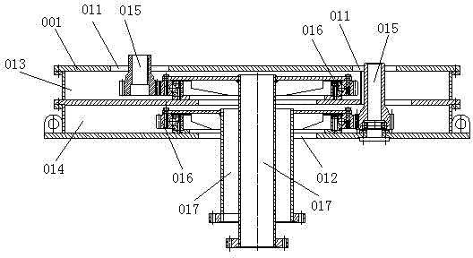
[0009] A driving device for a shaft-type stirring mud scraper, including a reducer case 001, two reducer output shaft connection holes 011 are opened on the upper cover of the reducer case 001, and one output hole is opened in the center of the bottom plate of the reducer case 001 012, the inner cavity of the reduction box 001 is divided into upper and lower chambers (013, 014), each chamber is provided with a transmission pinion 015 and a passive large gear 016 that mesh with each other, and the transmission of each chamber is small The end of the gear 015 corresponds to the reducer output shaft connection hole 011 on the upper cover of the reducer case 001; the center of the passive gear 016 in each layer of the chamber is coaxially connected to the transmission shaft 017, and each transmission shaft 017 passes through the reduction gear The output hole 012 in the center of the bottom plate of the chassis 001 is set to be nested with each other.


PUM


Abstract

The invention discloses a spigot shaft type stirring mud scraper driving device which comprises a speed reducer case, wherein at least two speed reducer outlet shaft connection holes are formed in an upper cover of the speed reducer case; an output hole is formed in the center of a base plate of the speed reducer case; the inner cavity of the speed reducer case is divided into at least two layers of cavities; a transmission pinion and a driven bull wheel which are meshed with each other are arranged in each cavity; the tail end of the transmission pinion in each layer of the cavity corresponds to each speed reducer outlet shaft connection hole in the upper cover of the speed reducer case; the center of the driven bull wheel of each layer of the cavity is connected with a transmission shaft; each transmission shaft penetrates through the output hole in the center of the base plate of the speed reducer case and is sleeved with the output hole. The occupied area of the driving device is greatly simplified; furthermore, the driving device is simple in structure and low in energy consumption.

Description

technical field [0001] The invention relates to the field of manufacturing a deceleration device, in particular to a deceleration device for an agitating mud scraper in a clarification tank. Background technique [0002] The driving device for the stirring mud scraper in the prior art generally includes a reducer and a motor connected to the reducer, but the reducer in the prior art generally only has one input hole and one output hole, and can only decelerate one motor. , it is impossible to concentrate two or two motors in one reducer box to decelerate separately, so the problem of the prior art is that the structure is complex and the floor space is large, especially on the mixing mud scraper for coaxial setting, although the current In order to solve this problem, some technologies propose to set the agitator and the mud scraper independently in the clarifier, but because the transmission shafts are different from each other, the mud scraper is driven by a pin tooth plat...

Claims


Application Information

Patent Timeline
Patent Type & Authority Applications(China)
IPC IPC(8): B01D21/20B01D21/24
Inventor 强成良陆叶陆姣王莉雅吴嘉欢
Owner JIANGSU YIHUAN GROUP
Features
  • R&D
  • Intellectual Property
  • Life Sciences
  • Materials
  • Tech Scout
  • Unparalleled Data Quality
  • Higher Quality Content
  • 60% Fewer Hallucinations
Learn More