
A welding device and method for brazing material, core tube and brazing material

A technology of welding device and welding method, which is applied in the direction of welding equipment, welding medium, auxiliary equipment, etc., can solve the problems that the brazing material cannot be laid neatly, the brazing material is easy to shake, and the labor cost is increased, so as to improve the brazing quality and overall Improve connection strength, save raw materials, and improve welding quality

Active Publication Date: 2020-12-22
远大可建科技有限公司
View PDF10 Cites 0 Cited by
  • Summary
  • Abstract
  • Description
  • Claims
  • Application Information

AI Technical Summary

Problems solved by technology

[0003] When the panel of the core plate is brazed to the core tube, there are mainly the following problems: (1) If the solder is directly laid on the core tube, when the panel is pressed on the core tube, due to the large area of ​​the panel, such as Using a 12m long panel, there will be airflow during the process of pressing and releasing, which will easily blow the brazing material, resulting in the inability to lay the brazing material neatly; (2) laying the brazing material directly will greatly waste raw materials and increase costs; (3) If If the brazing material is directly set on the core tube, the brazing material is also prone to shaking, which affects the brazing quality; (4) If the brazing material is set on the core tube manually, it will take time and effort, greatly reducing work efficiency, and increase labor cost

Method used


Image

  • A welding device and method for brazing material, core tube and brazing material
  • A welding device and method for brazing material, core tube and brazing material
  • A welding device and method for brazing material, core tube and brazing material

Examples


Embodiment 1

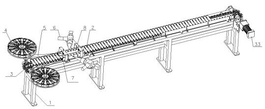
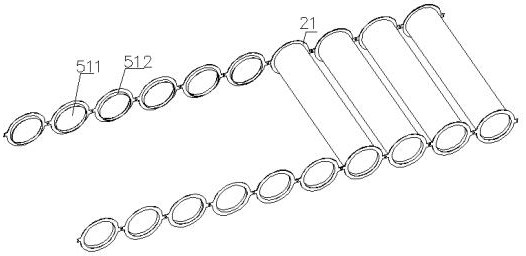
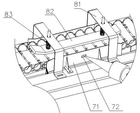
[0047] Such as figure 1 and figure 2 Shown: a welding device for a core tube and solder, including a frame 1, on which is provided a chain conveying mechanism 3 for conveying the core tube 2, one side of the chain conveying mechanism 3 is connected to a chain drive motor 33. Both sides of the entrance of the chain conveying mechanism 3 are provided with material boxes 4 respectively, and brazing material 5 is wound on the material boxes 4 . The core tube is arranged laterally on each sprocket 31 of the chain conveying mechanism, and the sprocket is provided with a groove 32 for accommodating the core tube. Lasers 6 are arranged on both sides of the conveying line of the chain conveying mechanism, and the lasers 6 on both sides face the two ends of the core tube 1, so that when the brazing material 5 is laid on the ends of the core tube 1, laser welding is carried out by the laser 6, Solder is integrally connected with each core tube. There are also guide mechanisms 7 on bo...

Embodiment 2

[0066] The difference from Embodiment 1 is that no pressing mechanism is provided at the position of the laser, and only the core tube is guided by the first guide plate.

[0067] Other structures are with embodiment 1.

Embodiment 3

[0069] The difference from Embodiment 1 is that the guide mechanism includes a first guide plate and a second guide plate, the first guide plate is arranged along the end of the core tube, and the second guide plate is connected with the first guide plate, and the brazing material flows from the first guide plate to the first guide plate. Pass through the gap between the guide plate and the second guide plate. Wherein the length of the first guide plate is greater than the length of the second guide plate, after the solder passes through the gap, it moves between the first guide plate and the end of the core tube, and the distance between the first guide plate and the end of the core tube It just makes the hole wall of the brazing filler metal insert into the core tube, so as to realize the tightness between the brazing filler metal and the core tube. In addition, the first guide plate is also used to guide and align each core tube so as to facilitate laser welding. Preferabl...


PUM


Abstract

The invention discloses brazing filler metal as well as a welding device and method for a core tube and the brazing filler metal. The welding device comprises a rack, wherein a conveying mechanism forconveying the core tube is arranged on the rack; an accommodating part for accommodating the core tube is arranged on the conveying mechanism; wound brazing filler metal are separately placed at thetwo sides of the inlet of the conveying mechanism; welders are arranged at the two sides of a conveying line of the conveying mechanism; each brazing filler metal ring of the brazing filler metal is connected to one core tube; and in a forward conveying process of the core tube, the core tube can be automatically inserted into the hole wall of the brazing filler metal ring, and is fixed by welding. The invention further discloses the brazing filler metal and the welding method for the core tube and the brazing filler metal. On one hand, dosage of the brazing filler metal can be saved, on the other hand, the automatic degree is high and welding quality is high.

Description

technical field [0001] The invention relates to the field of welding technology, in particular to a welding device and method for solder, a core tube and solder. Background technique [0002] The core board designed by our factory includes the first panel, the second panel and several core tubes arranged between the first panel and the second panel. The core tube and the two panels are connected by brazing. The produced core board can be used in various fields such as building structures, vehicles, ships, aircraft, aerospace equipment, containers, bridges, roads, tunnels, rail foundations, furniture, culverts, vacuum tubes or bags. [0003] When the panel of the core plate is brazed to the core tube, there are mainly the following problems: (1) If the brazing material is directly laid on the core tube, when the panel is pressed on the core tube, due to the large area of ​​the panel, such as Using a 12m long panel, there will be airflow during the pressing and releasing proc...

Claims


Application Information

Patent Timeline
Patent Type & Authority Patents(China)
IPC IPC(8): B23K35/14B23K3/08B23K3/06B23K1/00
CPCB23K1/0008B23K3/0623B23K3/08B23K35/0222
Inventor 张跃徐国新宋飞跃陈榆
Owner 远大可建科技有限公司
Learn More