Tray structure of photoresist homogenizer

A coating machine and tray technology, applied in the direction of coating, surface coating liquid devices, etc., can solve the problems of photoresist film uniformity deterioration, damage to the coating table, and insufficient suction at the vacuum suction port, etc., to achieve Avoid damage, avoid insufficient suction or blockage, and have the effect of large glue storage

Inactive Publication Date: 2014-04-02
NANTONG UNIVERSITY
View PDF6 Cites 9 Cited by
  • Summary
  • Abstract
  • Description
  • Claims
  • Application Information

AI Technical Summary

Problems solved by technology

[0002] The existing photoresist leveling table adopts the method of vacuum suction to absorb the silicon wafer, but the existing silicon wafer holder cannot effectively prevent the photoresist from penetrating into the vacuum suction port during the shaking process, such as figure 1 In the prior art shown, the silicon wafer is in direct contact with the vacuum suction port. During the high-speed rotation of the homogenizer, the photoresist is expanded into a thin film by the combined action of rotating centrifugal force and surface tension. The glue drops thrown out to the edge of the silicon wafer, due to the pressure difference between the edge of the silicon wafer and the suction port of the wafer table and the surface tension of the colloid, part of the glue droplets on the edge of the silicon wafer will be sucked into the vacuum suction piece along the back of the silicon wafer In the mouth, thereby blocking the vacuum suction port, resulting in insufficient suction of the vacuum suction port, resulting in poor uniformity of the photoresist film, and at the same time causing damage to the coating table

Method used


Image

  • Tray structure of photoresist homogenizer
  • Tray structure of photoresist homogenizer
  • Tray structure of photoresist homogenizer

Examples


Embodiment Construction

[0014] The preferred embodiments of the present invention will be described in detail below in conjunction with the accompanying drawings, so that the advantages and features of the present invention can be more easily understood by those skilled in the art, so as to define the protection scope of the present invention more clearly.

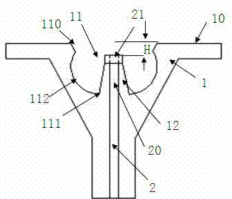
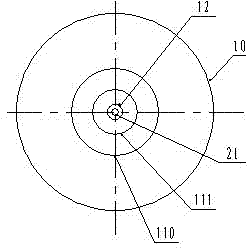
[0015] see figure 2 and image 3 , the embodiment of the present invention includes:

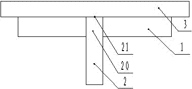
[0016] A kind of tray structure of glue homogenizer, comprising: silicon wafer supporting platform 1 and vacuum sucking structure 2, the top of described silicon wafer supporting platform 1 has a silicon wafer bearing plane 10, and described silicon wafer bearing plane 10 is a circle Shaped horizontal plane, a glue storage tank 11 is provided inwardly along the center of the silicon wafer bearing plane 10, and the groove wall 112 of the glue storage tank 11 is inwardly recessed in an arc shape, and in the glue storage tank 11 is also provided with a truncate...


PUM


Abstract

The invention discloses a tray structure of a photoresist homogenizer. The tray structure comprises a silicon wafer bearing table and a vacuum wafer suction structure, wherein a silicon wafer bearing plane is arranged at the top end of the silicon wafer bearing table; a photoresist storage groove is formed inwards along the center of the silicon wafer bearing plane; the groove wall of the photoresist storage groove is shaped like an inwardly-concave circular arc; a circular-truncated-cone-shaped boss is arranged in the middle of the photoresist storage groove; the vacuum wafer suction structure comprises an upper end and a vacuum wafer suction opening; the vertical distance between the vacuum wafer suction opening and the silicon wafer bearing plane is greater than 3mm. Through the mode, photoresists can be effectively prevented from being sucked into the vacuum wafer suction opening through the tray structure of the photoresist homogenizer, so that insufficient suction force or blocking of the vacuum wafer suction opening, caused by suction of the photoresists, is avoided; meanwhile, owing to the large-capacity photoresist storage groove, a large number of photoresists which are thrown away can be stored, and the photoresists flowing into the photoresist storage groove are prevented from being thrown away again, so that a photoresist homogenizing table is prevented from being damaged.

Description

technical field [0001] The invention relates to the field of glue homogenizer equipment, in particular to a glue homogenizer tray structure. Background technique [0002] The existing photoresist leveling table adopts the method of vacuum suction to absorb the silicon wafer, but the existing silicon wafer holder cannot effectively prevent the photoresist from penetrating into the vacuum suction port during the shaking process, such as figure 1 In the prior art shown, the silicon wafer is in direct contact with the vacuum suction port. During the high-speed rotation of the homogenizer, the photoresist is expanded into a thin film by the combined action of rotating centrifugal force and surface tension. The glue drops thrown out to the edge of the silicon wafer, due to the pressure difference between the edge of the silicon wafer and the suction port of the wafer table and the surface tension of the colloid, part of the glue droplets on the edge of the silicon wafer will be su...

Claims


Application Information

Patent Timeline
Patent Type & Authority Applications(China)
IPC IPC(8): B05C11/08B05C11/10
Inventor 花国然王强朱海峰徐影邓洁
Owner NANTONG UNIVERSITY
Why Eureka
Try Eureka