Vacuum boosting system, electric vehicle and vacuum boosting control method

A technology of vacuum boost and control method, applied in vehicle parts, brakes, brake transmissions, etc., can solve the problems of application limitation, shortened service life of electric vacuum pump, affecting service life, etc., so as to facilitate driving safety, improve service life, Energy saving effect

Inactive Publication Date: 2014-04-02
BEIQI FOTON MOTOR CO LTD
View PDF6 Cites 8 Cited by
  • Summary
  • Abstract
  • Description
  • Claims
  • Application Information

AI Technical Summary

Problems solved by technology

[0004] However, the batteries used in electric vehicles currently have low energy consumption. If the electric vacuum pump on the electric vehicle continuously pumps vacuum like the mechanical vacuum pump connected to the fuel engine, it will cause unnecessary waste of energy
[0005] In addition, the brake system usually requires a safe range of vacuum degree of 50bar to 80bar. Therefore, every time a safety brake is performed (stepping on the brake), the electric vacuum pump works once. If the electric vacuum pump does not work at this time, then the second safety brake After that, the vacuum degree in the vacuum booster will quickly drop to the lower limit of the safe range, thus greatly reducing the safety of electric vehicles
In addition, in view of the fact that electric vehicles are mostly used in urban traffic and sanitation, the number of braking is relatively frequent, so the electric vacuum pump will be started frequently, and the service life of the electric vacuum pump will be significantly reduced
In particular, when an electric vehicle brakes on a road that goes down a long slope continuously, the electric vacuum pump will always work, causing the temperature of the electric vacuum pump to be too high, which seriously affects its service life
Therefore, the application of this control method is greatly limited
Furthermore, since the vacuum booster of the large-tonnage hydraulic brake vehicle consumes more vacuum every time it works, this control method cannot meet the requirements of the large-tonnage hydraulic brake vehicle.
Therefore, this control method is only applied to N1 or M1 vehicles with light load.

Method used


Image

  • Vacuum boosting system, electric vehicle and vacuum boosting control method

Examples


Embodiment Construction

[0028] Specific embodiments of the present invention will be described in detail below in conjunction with the accompanying drawings. It should be understood that the specific embodiments described here are only used to illustrate and explain the present invention, and are not intended to limit the present invention.

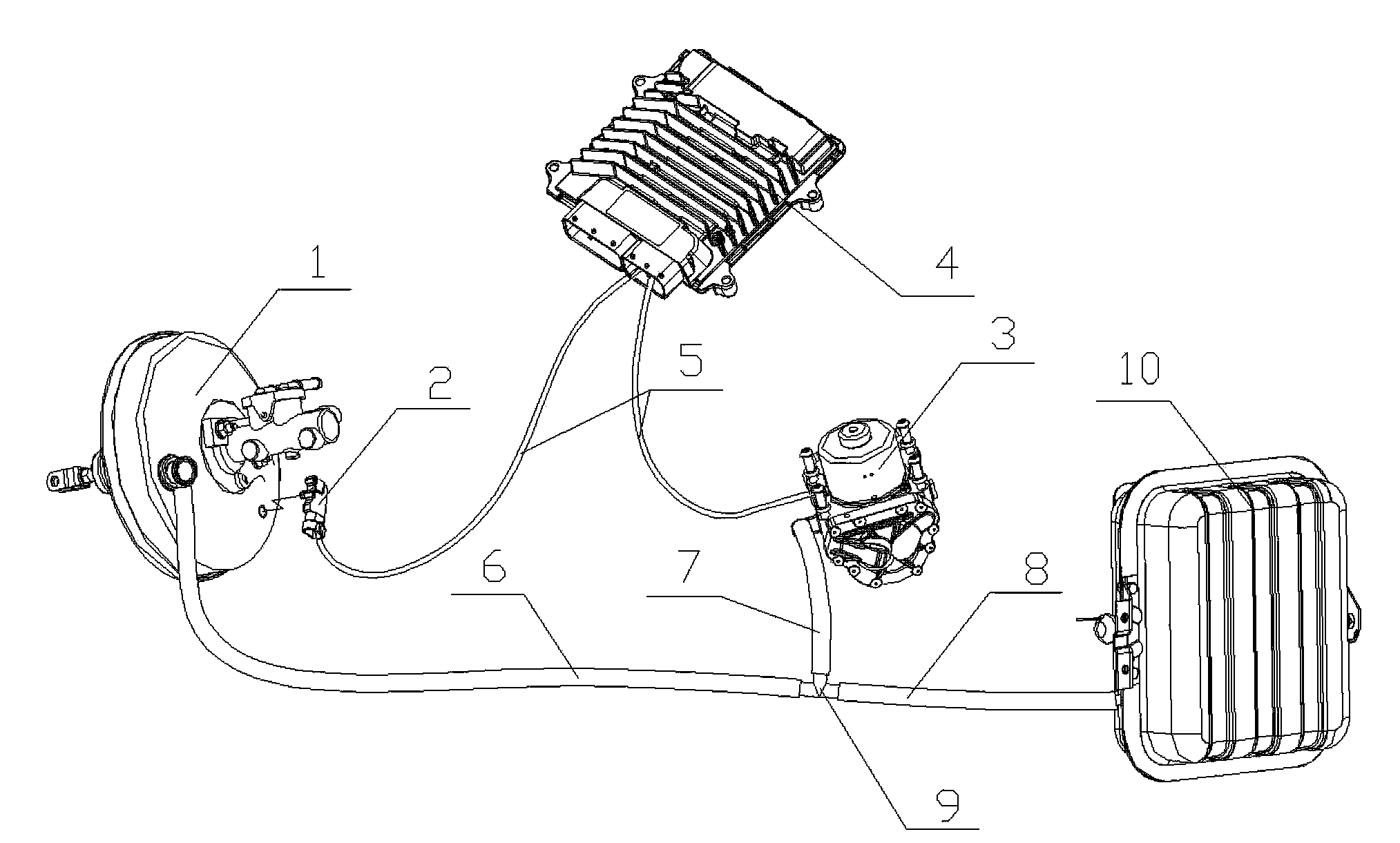
[0029] The vacuum booster system provided by the present invention, such as figure 1 As shown, it includes a vacuum booster 1 , and also includes a vacuum sensor 2 , an electric vacuum pump 3 , a control unit 4 and a vacuum tank 10 . The vacuum sensor 2 is arranged on the vacuum booster 1, and the vacuum booster 1 is used to collect the vacuum degree in the vacuum booster 1. The control unit 4 is electrically connected with the vacuum sensor 2 and the electric vacuum pump 3 respectively, and the electric vacuum pump 3 passes through the pipeline They are connected to the vacuum booster 1 and the vacuum tank 10 respectively, and the vacuum tank 10 communicates w...


PUM


Abstract

The invention disclose a vacuum boosting system, which comprises a vacuum booster (1), a vacuum degree sensor (2), an electric vacuum pump (3), a control unit (4) and a vacuum tank (10), wherein the vacuum degree sensor (2) is arranged on the vacuum booster (1), and is used for acquiring the vacuum degree in the vacuum booster (1); the control unit (4) is electrically connected with the vacuum degree sensor (2) and the electric vacuum pump (3) respectively; the electric vacuum pump (3) is connected with the vacuum booster (1) and the vacuum tank (1) through pipelines respectively; the vacuum tank (10) is communicated with the vacuum booster (1). Moreover, the invention further provides an electric vehicle comprising the vacuum boosting system, and a corresponding vacuum boosting control method. By adopting the vacuum boosting system, the electric vacuum pump can be prevented from being started frequently, and the service life of the electrically-controlled vacuum pump is prolonged remarkably.

Description

technical field [0001] The invention relates to the field of automobile braking, in particular to a vacuum booster system. In addition, the present invention also relates to an electric vehicle comprising the above-mentioned vacuum assist system. Further, the present invention also relates to a vacuum booster control method. Background technique [0002] For electric vehicles using hydraulic brakes, a vacuum booster is generally used in the hydraulic brake system to increase the pressure of the pipeline to obtain the required braking force. The vacuum booster needs vacuum as an energy source, so the vacuum pump in the vacuum booster system sucks the gas in the vacuum booster when it works, so as to keep the vacuum degree of the vacuum used in the braking system within a safe range to ensure the vehicle driving safety. When the vacuum degree is lower than the lower limit of the safety range, the effect of the vacuum booster will be significantly reduced, which will cause s...

Claims


Application Information

Patent Timeline
Patent Type & Authority Applications(China)
IPC IPC(8): B60T13/52B60T13/72
Inventor 张政王智博曹立臣
Owner BEIQI FOTON MOTOR CO LTD
Why Eureka
Try Eureka