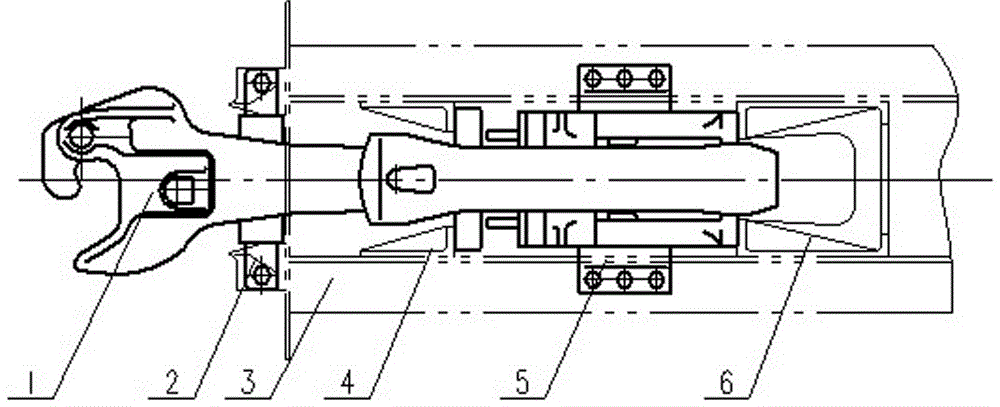
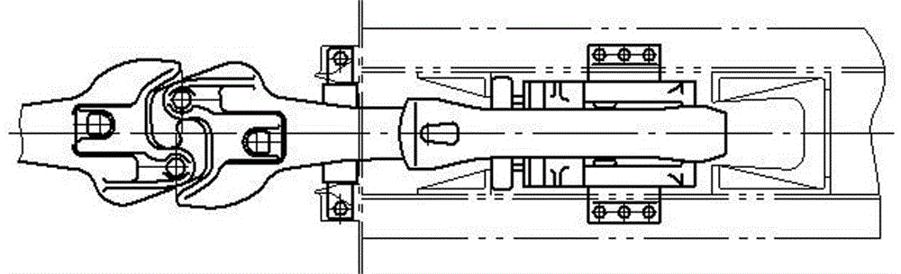
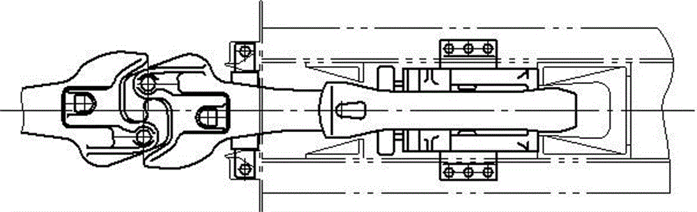
Neck type coupler

A coupler and coupler body technology, which is used in railway car body parts, railway couplings, transportation and packaging, etc., can solve the problem of high center of gravity height of empty vehicles and heavy vehicles, large wear of hook pin holes and hook tail pins, etc. Poor wear resistance and other problems, to achieve great economic and social benefits, reduce maintenance workload, and improve the effect of dynamic performance

Active Publication Date: 2016-06-08
CRRC TAIYUAN CO LTD
View PDF7 Cites 0 Cited by
  • Summary
  • Abstract
  • Description
  • Claims
  • Application Information

AI Technical Summary

Problems solved by technology

[0004] The structure of the above-mentioned couplers is straight, that is, the center line of the coupler head coincides with the center line of the coupler body. Since the height (empty car) of the railway freight car coupler from the rail surface is required to be 880mm, the floor of the railway freight car equipped with the above-mentioned couplers The height of the surface or container bearing surface from the rail surface is generally more than 1080mm, which makes the height of the center of gravity of the vehicle empty and heavy, which affects the dynamic performance of the vehicle
[0005] At the same time, with the further development of heavy-duty railway transportation in my country, the weight of railway freight vehicles continues to increase, from 60t and 70t to the current 80t. If the distance is more than 100mm, when the coupler is connected, the amount of overlap of the tongue traction part becomes smaller, and the phenomenon of coupler separation is gradually increasing, which affects the orderly progress of railway freight transportation and restricts the development of heavy-duty speed-up to a certain extent. When there is a large difference in coupler height between empty and heavy vehicles (the relative displacement of the knuckles of two connected trailer couplers in the vertical direction is large), effective measures must be taken to improve the reliability of coupler separation when the vehicle passes through a vertical curve
[0006] At present, the 16 and 17 couplers widely used in 70t class trucks in my country are rigid couplers. When the height difference is large and the vehicle passes through a vertical curve, it cannot meet the needs of vehicle linkage
[0007] In addition, there are no bushings in the coupler pin holes of existing couplers in my country. Although the surface has been quenched to increase the surface hardness, its wear resistance is still not good due to the large wear between the coupler pin hole and the coupler pin. Meet the requirements of daily use
In addition, after the tail pin hole of the coupler is worn, only traditional maintenance methods such as welding repair processing, which are difficult to control the quality and damage the body, are inconvenient for inspection and maintenance, affecting the maintenance efficiency and quality, and are not suitable for the requirements of replacement repairs and state-of-the-art repairs
[0008] A wear plate is installed under the coupler body to prevent the wear of the coupler body, but the wear plate of the existing coupler body is made of Q235-A material, which has poor wear resistance and short service life, which increases the workload and cost of maintenance
[0009] The tail end of the existing 13 series coupler is flat, which can keep the coupler in the right position during operation, but its curve passing performance is poor; the tail of the existing 16 and 17 couplers is spherical, and the curve passing performance is better. But the ability to maintain the upright position is slightly poor
At the same time, the cross-sectional size of the 13 series coupler body is small, the distance between the end of the coupler tail and the edge of the coupler pin hole is small, and the tensile failure strength of the coupler body is 3100kN. In daily use, the coupler body often has bending deformation or cracks. Faults have brought safety hazards to the use of vehicles

Method used


Image

  • Neck type coupler
  • Neck type coupler
  • Neck type coupler

Examples


Embodiment Construction

[0037] The specific embodiment of the present invention will be further described in conjunction with the accompanying drawings.

[0038] a. Raise the coupler head so that the horizontal centerline of the coupler head is higher than the horizontal centerline of the coupler body, and reduce the distance between the floor surface of the railway freight car or the container bearing surface and the rail surface on the basis of satisfying the coupling height (880mm for empty car) Height and center of gravity height of empty and heavy vehicles. At the same time, when the vehicle is subjected to a strong impact and the compression of the buffer is large, the hook body of the coupler is prevented from being stuck by the contact with the top of the impact seat of the coupler, so that the shoulder of the coupler is first in contact with the impact seat. The elevation angle of the raised part of the coupler body is set to 12~16°, preferably 16°, the distance from the starting point of t...


PUM


Abstract

The invention belongs to the technical field of a car hook for a railway wagon and specifically relates to a neck pitching type car hook. The problems of the present car hook are solved. The neck pitching type car hook comprises a hook head, a hook body and a hook tail, wherein a horizontal central line of the hook head is pitched up and is 35-50 mm higher than the horizontal central line of the hook body; a pitching part is arranged on the front part of the hook body and is connected with the hook head; a downward extending type anti-falling platform is arranged on the lower part of a hook tongue of the hook head; the inner and outer outlines of the downward extending type anti-falling platform are the same as the outline of a hook tongue drawing surface of the car hook; a rib platy platform is arranged at the bottom of the downward extending type anti-falling platform. The neck pitching type car hook has the advantages that the distance from the floor surface of the railway wagon or the bearing surface of a container to a rail surface and the height of the center of gravity of an empty and load car are suitably reduced, the loading and unloading for goods or containers are convenient and the dynamic property of the car is increased.

Description

technical field [0001] The invention belongs to the technical field of couplers for railway wagons, and in particular relates to a neck-up coupler. Background technique [0002] The purpose of the railway wagon coupler is to connect the railway wagons and locomotives through it, form trains, and transmit the traction generated between trains during operation or shunting and formation operations. [0003] At present, the couplers used for railway freight cars in my country can be divided into two types: rigid couplers and non-rigid couplers according to the mutual relationship after being connected. Rigid coupler means that the two couplers cannot move up and down relative to each other in the vertical direction after being connected together. The requirements for the vehicle to be connected when the vehicle passes through the vertical curve, such as the 16 and 17 couplers used by the speed-up and heavy-duty trucks in our country. The non-rigid coupler means that the two co...

Claims


Application Information

Patent Timeline
Patent Type & Authority Patents(China)
IPC IPC(8): B61G3/10
Inventor 刘文胜谢剑锋秦忠义刘俊雷张春发郭树平吴秀娟
Owner CRRC TAIYUAN CO LTD
Why Eureka
Try Eureka