Heavily-loaded vehicle cab rear suspension device

A technology for trucks and cabs, which is applied to the superstructure, vehicle parts, transportation and packaging of trucks, can solve the problems of complex structure, large installation space, damaged spring shock absorbers, etc., to expand maintenance space, Increased installation space and reduced vibration frequency

Inactive Publication Date: 2014-04-02
浙江玉强机械股份有限公司
View PDF6 Cites 9 Cited by
  • Summary
  • Abstract
  • Description
  • Claims
  • Application Information

AI Technical Summary

Problems solved by technology

[0004] This type of suspension lacks a device to limit the up and down travel of the spring shock absorber. When the cab is under too much load, the vertical deformation of the spring shock absorber will also be too large, which may exceed the allowable deformation, thereby damaging the spring shock absorber. The vibrator needs to be replaced and maintained, and its service life is short. Although the spring damper with this structure can also buffer and reduce the vibration force, it still cannot reduce the vibration frequency of the cab, and the comfort level is still low.
The suspended left and right lower connecting brackets of this structure are connected by a beam. Although the beam is made into a curved shape, there is still the problem of occupying a large installation space. It is easy to hit the beam with the head when performing maintenance. Moreover, since the beam is installed and occupies a large installation space, it is not conducive to the configuration and installation of other components.
The suspension left and right lower connecting brackets of this structure are formed by casting, the structure is complicated, and the processing is difficult. In addition, the manufacturing cost of the beam makes the production cost of the whole set of rear suspension device relatively high, and the economic benefit is poor.

Method used


Image

  • Heavily-loaded vehicle cab rear suspension device
  • Heavily-loaded vehicle cab rear suspension device
  • Heavily-loaded vehicle cab rear suspension device

Examples


Embodiment Construction

[0026] The following are specific embodiments of the present invention and in conjunction with the accompanying drawings, the technical solutions of the present invention are further described, but the present invention is not limited to these embodiments.

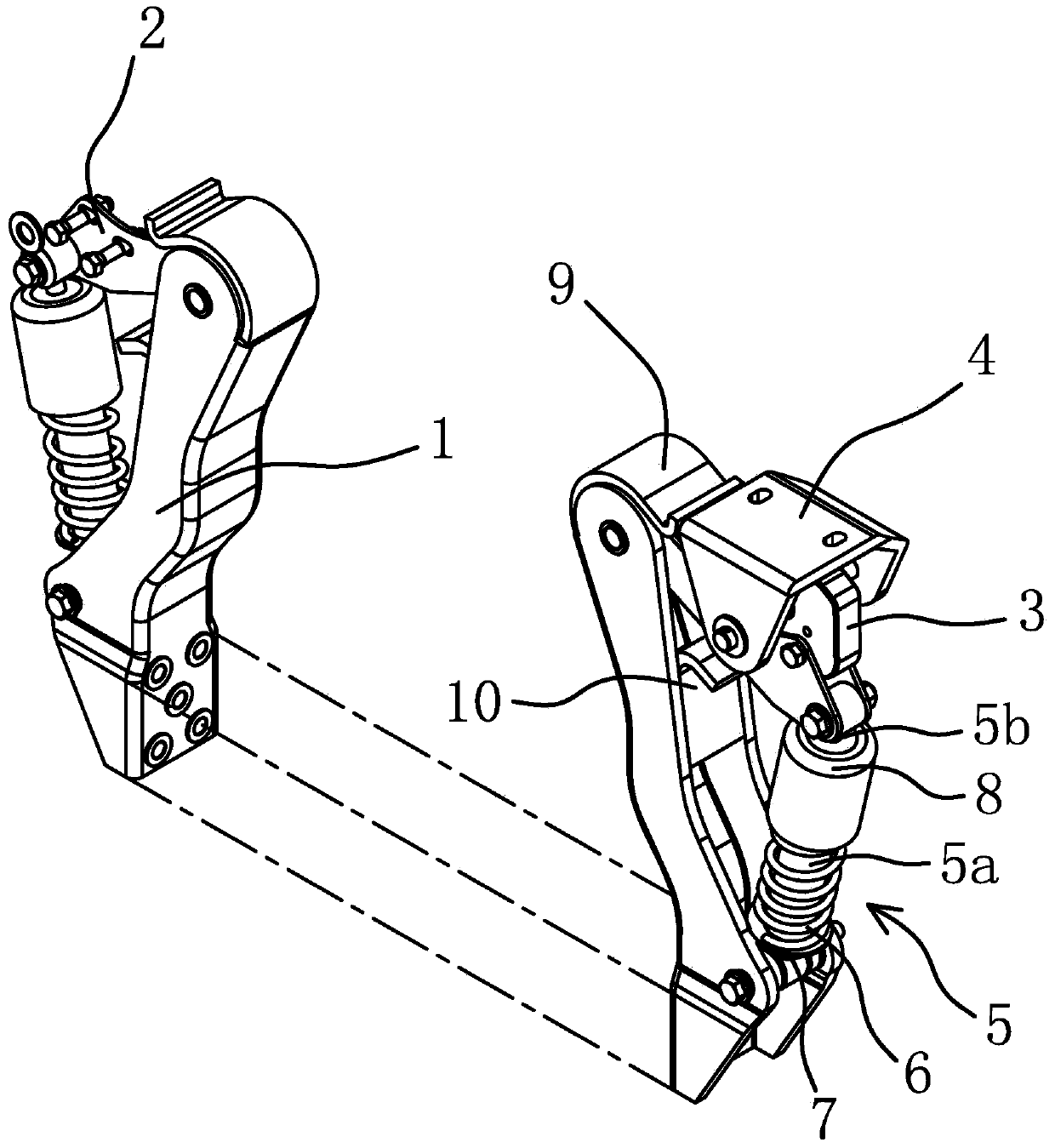
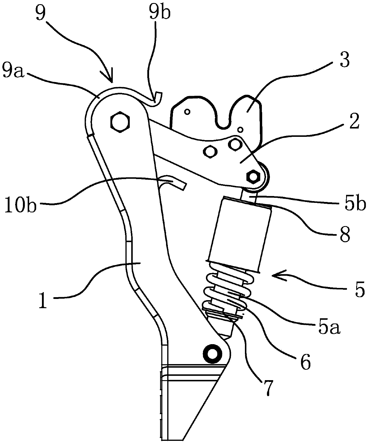
[0027] Such as figure 1 , figure 2 As shown, the truck cab rear suspension device includes a bracket 1, a rocker arm 2, a lock bolt 3, a connecting block 4, a damping shock absorber 5, a spring 6, an upper limit block 9 and a lower limit block 10.

[0028] Bracket 1 is a stamped part, two in number, arranged symmetrically from left to right, and made by stamping, bending, and punching. They are respectively fixed at both ends of the main beam of the car, and the part above the lower end of the bracket 1 is slightly inclined towards the inside as a whole, that is, the distance between the tops of the two brackets 1 is smaller than the distance between the bottoms. The upper end of the bracket 1 has a hinge hole, through ...


PUM


Abstract

The invention provides a heavily-loaded vehicle cab rear suspension device, belongs to the technical field of machinery and solves the problem that existing suspension devices are complex in structure, large in mounting occupation space, low in comfortableness and the like. The device comprises a pair of supports in left-right symmetry, a pair of damping shock absorbers and a pair of springs, a pair of rocker arms is hinged at the upper end of each support, a lock bolt is connected between each pair of the rocker arms, a connecting block is arranged on each lock bolt and used for being fixedly connected with a cab, the lower end of each support is fixedly connected with a crossbeam of a vehicle, each damping shock absorber comprises a cylinder and a piston rod, the inner end of each piston rod is positioned in the corresponding cylinder while the outer end of the same extends out of the cylinder to be hinged with the corresponding pair of the rocker arms, the bottom of each cylinder is hinged to the middle lower end of the corresponding support, each spring is sleeved on the corresponding damping shock absorber, and one end of each spring is abutted against the corresponding cylinder while the other end of the same is abutted against the corresponding piston rod. The heavily-loaded vehicle cab rear suspension device has the advantages of convenience for processing, low production cost, small mounting occupation space and the like.

Description

technical field [0001] The invention belongs to the technical field of machinery, and relates to a truck, in particular to a rear suspension device for a cab of the truck. Background technique [0002] With the development of my country's transportation industry and the continuous increase in highway construction mileage, more and more users choose automobile long-distance transportation as the main way of material transportation. When the vehicle is running at high speed, the vibration transmitted to the cab by the road surface through the suspension system and the vibration transmitted to the cab by the engine and transmission system will make the driver feel uncomfortable. [0003] In order to improve the comfort of the vehicle and alleviate driving fatigue, some floating suspension devices are currently used on the cab of the vehicle. For example, the Chinese patent literature discloses a full-floating rear suspension device for the cab [Patent No. 200620095446.8; Author...

Claims


Application Information

Patent Timeline
Patent Type & Authority Applications(China)
IPC IPC(8): B62D33/10
Inventor 叶尚云
Owner 浙江玉强机械股份有限公司
Why Eureka
Try Eureka