Automatic canopy

An automatic technology for awnings, applied in the field of awnings, can solve problems such as unfavorable light

Inactive Publication Date: 2014-04-02
HUANGSHI GOLD INNOVATION INVESTMENT MANAGEMENT
View PDF0 Cites 14 Cited by
  • Summary
  • Abstract
  • Description
  • Claims
  • Application Information

AI Technical Summary

Problems solved by technology

[0002] Existing residential windows are equipped with rainproof sheds to prevent rainwater from floating int

Method used


Image

  • Automatic canopy

Examples


Embodiment Construction

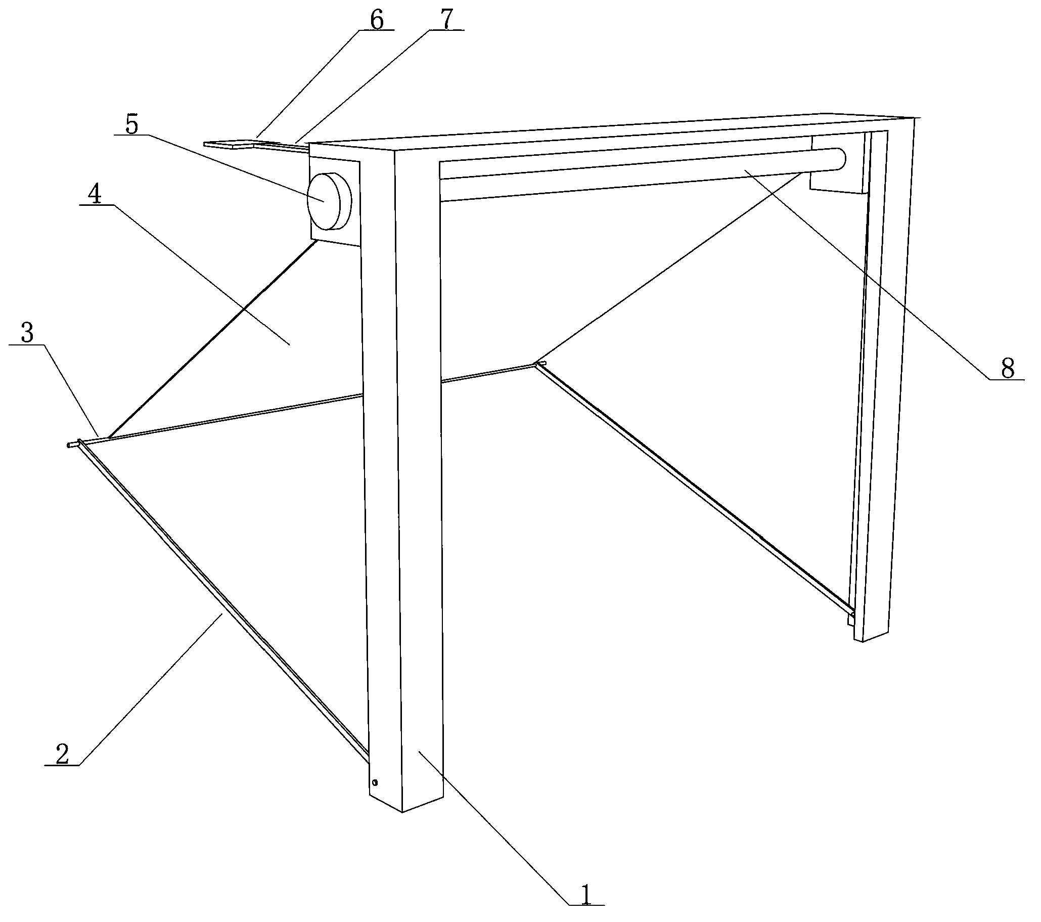
[0009] Explanation of symbols in the drawings: bracket 1, support rod 2, guide rod 3, waterproof cloth 4, motor 5, humidity sensor 6, chip 7, rotating shaft 8.

[0010] The technical solution of the automatic rain shelter according to the embodiment of the present invention will be described in detail below in conjunction with the accompanying drawings.

[0011] Such as figure 1 As shown, the automatic rain shelter includes a bracket, a control component and a rain-shielding component. The control component is provided with a humidity sensor 6 and a chip 7. The rain-shielding component is composed of a support rod 2, a guide rod 3, a waterproof cloth 4, a 5 and the rotating shaft 8, the chip 7 is connected to the motor 5 circuit, the humidity sensor 6 is connected to the chip 7 circuit,

[0012] The top end of the waterproof cloth 4 is fixedly connected to the rotating shaft 8, and the bottom end is fixedly connected to the guide rod 3,

[0013] The two ends of the guide rod...


PUM


Abstract

The invention discloses a rain-shedding device, in particular to an automatic canopy, which comprises a bracket, a control assembly, a rain-shedding assembly, wherein the control assembly is provided with a moisture sensor and a chip; the rain-shedding assembly consists of a support rod, a guide rod, water-proof cloth, a motor and a revolving shaft; the control assembly is in circuit connection with the motor; one end of the water-proof cloth is fixedly connected with the revolving haft, and the other end of the water-proof cloth is fixedly connected with the guide rod; the two ends of the guide rod are rotationally connected with the support rod; the support rod is rotationally connected with the bottom end of the bracket. The automatic canopy disclosed by the invention can react automatically according to the change of the weather by using the moisture sensor and control the canopy to be opened and closed, so that rain water is prevented from wetting clothes or running indoors.

Description

technical field [0001] The invention relates to an automatically retractable rain shelter used for shielding rain outside a window. Background technique [0002] Existing dwelling house windows are all provided with the rain-proof shelter that prevents rainwater from floating into the window, but all are fixedly arranged on the wall, which is unfavorable for indoor illumination when sunny. Contents of the invention [0003] In order to overcome the disadvantages of the existing rain shelter, the present invention aims to provide an automatically retractable rain shelter. [0004] The present invention adopts the following technical solutions to achieve the above object. [0005] The automatic rain shelter includes a bracket, a control component and a rain-shielding component, and is characterized in that: the control component is provided with a humidity sensor and a chip, and the rain-shielding component is composed of a support rod, a guide rod, a waterproof cloth, a mo...

Claims


Application Information

Patent Timeline
IPC IPC(8): E04F10/06
CPCY02B80/50Y02A30/24Y02B80/00
Inventor 不公告发明人
Owner HUANGSHI GOLD INNOVATION INVESTMENT MANAGEMENT
Why Eureka
Try Eureka