Oil-gas separator for supercharged engine

A technology of oil-gas separator and supercharged engine, which is applied in the direction of engine lubrication, engine components, machines/engines, etc. It can solve the problems of difficult maintenance, low separation efficiency of oil-gas separator, complicated disassembly process, etc., and reduce oil consumption Quantity, beneficial to the overall layout, and the effect of reducing the layout space

Active Publication Date: 2014-04-02
CHONGQING CHANGAN AUTOMOBILE CO LTD
View PDF7 Cites 11 Cited by
  • Summary
  • Abstract
  • Description
  • Claims
  • Application Information

AI Technical Summary

Problems solved by technology

[0004] First, a labyrinth oil-gas separator composed of baffles is used; in order to achieve a good separation effect, the oil-gas separator needs more baffles, which takes up a lot of space and is not conducive to the miniaturization and overall layout of the engine; at the same time, the more baffles , when the engine is running at high speed, the pressure in the crankcase is high, and it is easy to make the oil return poor
[0005] Second: Filter-type oil-gas separator; it separates engine oil and gas by filtering. The separation efficiency of this kind of oil-gas separator is low. When there is a lot of oil-gas mixture to be separated, the oil-gas separation is not complete and the effect is not good.
[0006] Third: the cyclone oil-gas separator; it contains many parts, the disassembly process is complicated, the maintenance is difficult, and the applicability is poor

Method used


Image

  • Oil-gas separator for supercharged engine
  • Oil-gas separator for supercharged engine
  • Oil-gas separator for supercharged engine

Examples


Embodiment Construction

[0018] The present invention will be further described below in conjunction with accompanying drawing.

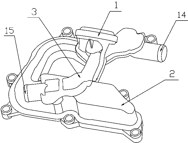
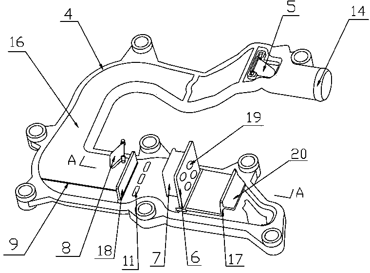
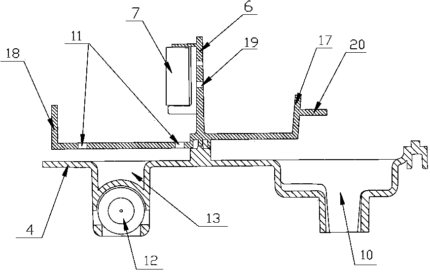
[0019] Such as figure 1 , figure 2 , image 3 The oil-gas separator of the boosted engine shown includes an oil-containing gas inlet 10 , an oil-gas separation passage 16 , an oil outlet 13 and a first gas outlet 14 connected in sequence, and the oil outlet 13 is connected with a funnel-shaped oil outlet 12 . in,

[0020] The oil-gas separation channel 16 is a U-shaped channel whose cross-sectional area gradually decreases along the flow direction of the oil-gas mixture formed by bonding the upper cover plate 2 and the lower cover plate 4; the oil-containing gas inlet 10, the oil outlet 13 and the first gas outlet 14 is arranged on the lower cover plate 4, and the oil-gas separation channel 16 is separated from the oil-containing gas inlet 10 by a partition 6 with a plurality of through holes 19, and the back of the partition 6 is provided with a filter element 7 facing...


PUM


Abstract

The invention discloses an oil-gas separator for a supercharged engine. The oil-gas separator comprises an oily gas inlet, an oil-gas separation passage, an oil outlet and a first gas outlet, which are sequentially communicated, wherein the oil-gas separation passage is formed by adhering an upper cover plate and a lower cover plate; the oily gas inlet and the oil outlet are formed in the lower cover plate; the oil-gas separation passage is a U-shaped passage of which the cross sectional area is gradually reduced along the flowing direction of an oil-gas mixture, and is separated from the oily gas inlet through a partition plate with through holes; a filter element opposite to the through holes is arranged on the back surface of the partition plate; a first baffle plate close to the oily gas inlet is arranged in front of the partition plate; a second L-shaped baffle plate is arranged behind the partition plate, and oil return holes are formed in the second baffle plate, and engine oil flows to the oil outlet through the oil return holes; an oil return groove is formed in the bottom of the oil-gas separation passage behind the second baffle plate, and the engine oil flows to the oil outlet through the oil return groove. According to the oil-gas separator, oil and gas can be more completely separated, the separation efficiency is improved, the consumption of the engine oil is lowered, the emission performance is improved, and the mounting space is reduced.

Description

technical field [0001] The invention belongs to the technical field of automobile engines, and in particular relates to an oil-gas separator for a supercharged engine. Background technique [0002] During the operation of the automobile engine, combustible mixed gas and exhaust gas will enter the crankcase, dissolve in the oil, dilute the oil, and deteriorate the performance. Pollutants such as particles contained in the exhaust gas will mix with the oil, causing the oil to deteriorate and corrode parts; At the same time, the engine generates heat, the oil volatilizes, and the internal pressure of the crankcase increases. The oil will leak from the crankcase oil seal and other places. The loss of engine oil will cause excessive oil consumption, and the steam generated by the volatilization of engine oil will also pollute the atmosphere. Therefore, the engine uses a crankcase ventilation system to remove crankcase blow-by, prevent oil deterioration, reduce oil consumpti...

Claims


Application Information

Patent Timeline
Patent Type & Authority Applications(China)
IPC IPC(8): F01M11/08
Inventor 殷智勇王显刚刘建东黄参朱玉明
Owner CHONGQING CHANGAN AUTOMOBILE CO LTD
Why Eureka
Try Eureka