
Support and direct-lit LED backlight module with same

A backlight module, direct-type technology, applied in the field of direct-type LED backlight modules, to achieve the effect of easy and quick replacement of light sources, simple bracket structure, avoiding the cost of procedures and man-hours

Inactive Publication Date: 2014-04-02
NANJING CEC PANDA LCD TECH
View PDF4 Cites 1 Cited by
  • Summary
  • Abstract
  • Description
  • Claims
  • Application Information

AI Technical Summary

Problems solved by technology

[0003] The purpose of the present invention is to solve the problems existing in the existing direct-type LED backlight module, and provide a bracket that can simply and quickly disassemble the light source to achieve the purpose of replacement and a direct-type LED backlight module using the bracket

Method used


Image

  • Support and direct-lit LED backlight module with same
  • Support and direct-lit LED backlight module with same
  • Support and direct-lit LED backlight module with same

Examples


Embodiment Construction

[0022] The present invention will be further described below in conjunction with the accompanying drawings and embodiments.

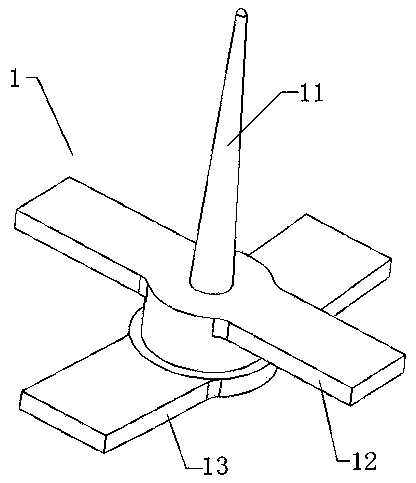
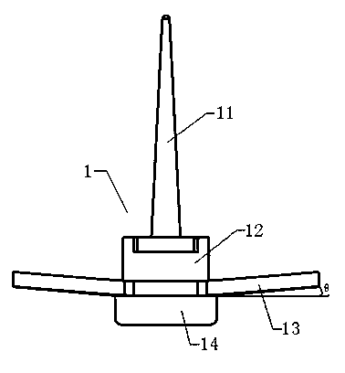
[0023] like Figure 2-3 As shown: a bracket, the bracket 1 includes a diffuser plate thimble 11, an upper clamping structure 12 and a lower clamping structure 13, the diffusion plate thimble 11 used to make a diffuser plate is located on the upper clamping structure 12, the upper clamping The engaging structure 12 is located above the lower engaging structure 13 and the two are staggered, the angle between the upper engaging structure 12 and the lower engaging structure 13 is 30°-90° and the length of the upper engaging structure 12 and / or The width is smaller than the length and / or width of the lower engaging structure 13 so as to stably clamp the LED light bar substrate 3 on the back plate 2 . In order to make the bracket easy to use, the lower engaging structure 13 is set with an upwardly set inclination angle θ and the inclination angle θ is 3° to ...


PUM


Abstract

The invention discloses a support. The support (1) comprises a diffuser push rod (11), an upper clamping structure (12) and a lower clamping structure (13). The diffuser push rod (11) is disposed above the upper clamping structure (12), the upper clamping structure (12) is disposed above the lower clamping structure (13), the upper clamping structure (12) and the lower clamping structure (13) are crossed, and the upper clamping structure (12) is shorter or narrower than the lower clamping structure (13). During use, an LED light bar base plate (3) is mounted in a light bar accommodating position at the back of a back plate (2), the upper clamping structure (12) penetrates the LED light bar base plate (3) and the back plate (2), and then the upper clamping structure (12) and the lower clamping structure (13) fix the LED light bar base plate (3) on the back plate (2) by turning the support (1). The support is simple in structure, and the backlight module with the same has the advantage that a light source can be detached easily and rapidly so as to be changed.

Description

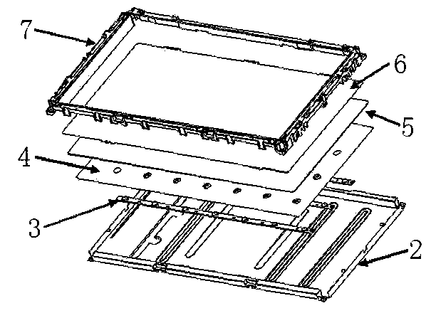
technical field [0001] The invention relates to the design field of backlight modules of liquid crystal displays, in particular to a bracket that can simply and quickly disassemble a light source to achieve the purpose of replacement and a direct-down LED backlight module using the bracket. Background technique [0002] Existing direct-lit LED backlight modules such as figure 1 As shown, the direct-type LED backlight module generally includes a backplane 2, an LED light bar substrate 3 on which an LED light source is placed, a reflector 4, a bracket, a diffusion plate 5, an optical film 6, a plastic frame 7, and the like. When the backlight module is assembled, the LED light strip substrate 3 is first installed on the backplane 2, the reflector 4 is covered on the LED light strip substrate 3, the bracket supporting the diffusion plate 5 is installed, and the diffusion plate 5, the optical film 6 and the The plastic frame 7 completes the backlight module, and finally instal...

Claims


Application Information

Patent Timeline
Patent Type & Authority Applications(China)
IPC IPC(8): F21V17/16F21Y101/02F21Y107/50F21Y115/10
Inventor 王世林
Owner NANJING CEC PANDA LCD TECH
Learn More