Detection range-adjustable current detection circuit and method

A technology for adjusting the circuit and detection range, which is applied in the field of signal detection, can solve the problems of digital signal processor influence, large detection error, and low current detection accuracy of the current detection circuit, and achieve the effect of improving the current detection accuracy

Inactive Publication Date: 2014-04-02
EAST GRP CO LTD
View PDF5 Cites 13 Cited by
  • Summary
  • Abstract
  • Description
  • Claims
  • Application Information

AI Technical Summary

Problems solved by technology

[0004] However, since the current generated by the photovoltaic cell has a large range of changes within a day, the circuit and method of current detection in the prior art will have a large detection error when the photovoltaic output current is small. When the value is larger, the detection voltage signal may exceed the limit value of the AD port of the digital signal processor. If the detection current signal collected by the current detection circuit is inaccurate, it will have a greater impact on the digital signal processor of the current detection circuit, resulting in The current detection accuracy of the current detection circuit is not high

Method used


Image

  • Detection range-adjustable current detection circuit and method
  • Detection range-adjustable current detection circuit and method
  • Detection range-adjustable current detection circuit and method

Examples


Embodiment 1

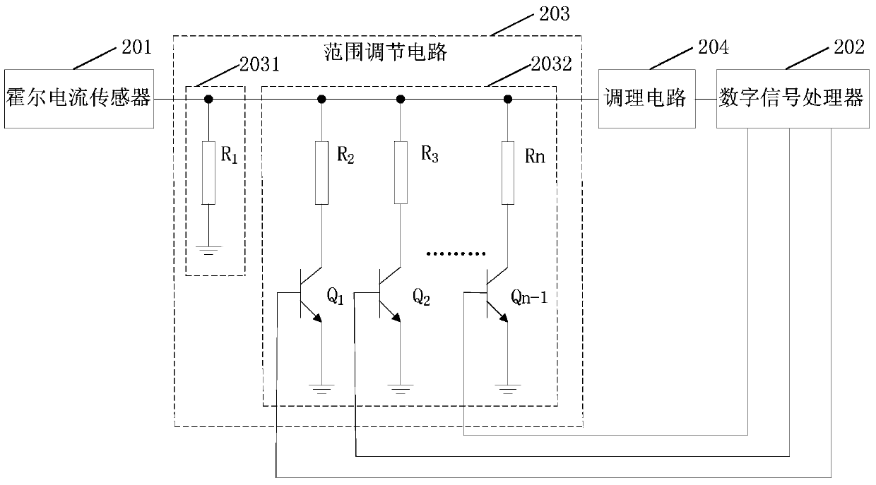
[0031] figure 2 is a schematic diagram of a current detection circuit with an adjustable detection range provided by the first embodiment of the present invention. The circuit provided in the embodiment of the present invention can implement the current detection method with adjustable detection range provided in any embodiment of the present invention. Such as figure 2 As shown, the circuit provided by the embodiment of the present invention includes:

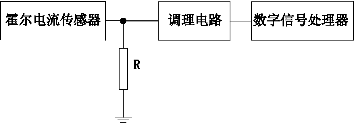
[0032] Hall current sensor 201.

[0033] In the photovoltaic inverter, the Hall current sensor is usually used to collect the photovoltaic output current signal, and output the sampling output current signal proportional to the photovoltaic output current signal, that is, the detection current signal. For the Hall sensor of known type, The ratio of the sampled output current signal to the photovoltaic output current signal is constant, that is Among them, I p To sample the photovoltaic output current signal, I s is th...

Embodiment 2

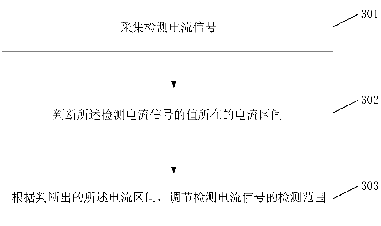
[0054] image 3 It is an implementation flowchart of the current detection method with adjustable detection range provided by the second embodiment of the present invention. This embodiment can be implemented by the current detection circuit with adjustable detection range provided by any embodiment of the present invention. Such as image 3 As shown, the method provided by the embodiment of the present invention includes:

[0055] Step 301, collecting detection current signals.

[0056] In the embodiment of the present invention, a Hall current sensor may be used to collect the detection current signal.

[0057] Preferably, before collecting and detecting the current signal, the method further includes: setting a current interval in advance; and determining a sampling resistance value corresponding to the current interval according to the current interval.

[0058] Step 302, judging the current interval where the value of the detected current signal is located.

[0059] ...


PUM


Abstract

The invention discloses a detection range-adjustable current detection circuit and method. The circuit comprises a hall current sensor, a digital signal processor and a range adjusting circuit, wherein the hall current sensor is used for collecting detection current signals; the digital signal processor is used for judging the current interval where the values of the detection current signals are positioned; the range adjusting circuit is used for adjusting the detection range of the detection current signals according to the judged current interval. According to the detection range-adjustable current detection circuit and method, the current detection precision of the current detection circuit can be improved.

Description

technical field [0001] The invention relates to the technical field of signal detection, in particular to a current detection circuit and method with an adjustable detection range used in a photovoltaic inverter. Background technique [0002] Photovoltaic inverter, also known as power regulator, is a power adjustment device composed of semiconductor devices. It is mainly used in photovoltaic power generation systems and can convert DC power generated by photovoltaic cells into AC power. For photovoltaic inverters, since the electric energy generated by photovoltaic cells changes within a day, it is generally small when it is started in the morning, then gradually increases, reaches the maximum at noon, and then gradually decreases until it is shut down due to insufficient energy at night. It can be seen that the current collected by the photovoltaic inverter has a large range of changes within a day. [0003] Such as figure 1 As shown, the current detection circuit and met...

Claims


Application Information

Patent Timeline
Patent Type & Authority Applications(China)
IPC IPC(8): G01R19/25
Inventor 陈书生
Owner EAST GRP CO LTD
Why Eureka
Try Eureka