A method and device for parallel connection of multiple partial discharge signals

A discharge signal and partial discharge technology, applied in the direction of testing circuits, electrical components, testing dielectric strength, etc., can solve the problems of signal energy attenuation, signal loss, and self-triggering one-way transmission, etc., to improve equipment operation safety, The effect of avoiding loss

Active Publication Date: 2016-08-31
SHANGHAI JIAO TONG UNIV
View PDF6 Cites 0 Cited by
  • Summary
  • Abstract
  • Description
  • Claims
  • Application Information

AI Technical Summary

Problems solved by technology

[0005] The disadvantage of scheme A is that the circulator isolates the reverse signal by absorbing signal energy. For non-selective transmission signals in multiple transmission signals, that is, other UHF signals transmitted from parallel connection branches in the signal bus , it will produce a large amount of signal energy attenuation when passing through the signal isolation circuit in the unidirectional transmission circuit based on the circulator, resulting in signal loss, and the signal energy is attenuated by 50%
[0007] The disadvantage of scheme B is: the general switch circuit cannot realize the self-triggering closing and turning off of the signal to control the switch, so it cannot realize self-triggering one-way transmission

Method used


Image

  • A method and device for parallel connection of multiple partial discharge signals
  • A method and device for parallel connection of multiple partial discharge signals
  • A method and device for parallel connection of multiple partial discharge signals

Examples


Embodiment 1

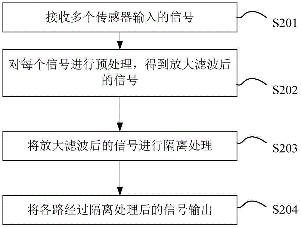
[0052] figure 2 This is a flowchart of a method for parallel connection of multiple partial discharge signals provided by an embodiment of the present invention.

[0053] Such as figure 2 As shown, the method includes the following steps:

[0054] Step S201: Receive signals input by multiple sensors.

[0055] The sensors include partial discharge UHF sensors, ultrasonic sensors, and high frequency current sensors, which respectively generate UHF sensing signals, ultrasonic signals, and high frequency current signals. That is, this step can be specifically: receiving multiple local UHF sensor inputs Ultra-high-frequency sensing signals from, ultrasonic sensing signals input by multiple ultrasonic sensors, and high-frequency current sensing signals input from multiple high-frequency current sensors.

[0056] Step S202: preprocessing each signal, including amplification and filtering, to obtain amplified and filtered signals. Among them, in the preprocessing of the partial discharge U...

Embodiment 2

[0070] On the basis of the first embodiment, the embodiment of the present invention also provides a parallel connection device for multiple partial discharge signals, such as Figure 4 Shown is a schematic diagram of a parallel connection device for multiple partial discharge signals provided by an embodiment of the present invention.

[0071] The parallel connection device for multiple partial discharge signals includes the following sub-devices:

[0072] The signal input interface 401 is used to receive signals input by multiple sensors.

[0073] The sensors include partial discharge UHF sensors, ultrasonic sensors, and high frequency current sensors, which respectively receive partial discharge UHF sensing signals, ultrasonic signals, and high frequency current signals. That is, the signal input interface 401 is specifically used to receive multiple partial discharge characteristics. Partial discharge ultra-high frequency sensing signals input by high-frequency sensors, ultrasoni...


PUM


Abstract

The invention discloses a method and device for parallel connection of multiple partial discharge signals, which receives signals input by multiple partial discharge sensors and performs preprocessing to obtain amplified signals, and performs isolation processing on the amplified signals so that the signals can be self-triggered and transmitted in one direction , and finally output the isolated and processed signals of each channel, wherein the delayed transmission of the UHF partial discharge signal is realized by using a surface acoustic wave delay line group. The present invention amplifies and isolates multi-channel signals so that the signals can be self-triggered for one-way transmission and isolation, thereby realizing interference-free parallel connection of multiple partial discharge signals and further avoiding signal loss during signal transmission. At the same time, since the partial discharge detection signals connected in parallel are all transmitted to the signal bus, one data acquisition device monitors multiple signals at the same time, thereby realizing data acquisition through the same set of data acquisition devices and reducing costs.

Description

Technical field [0001] The invention belongs to the technical field of signal control, and particularly relates to a method and device for parallel connection of multiple partial discharge signals. Background technique [0002] In the detection of partial discharge signals, multiple UHF pulse signals are connected in parallel on a transmission bus for transmission. At any interface that merges into the transmission bus, it is necessary to realize the transmission of the merged signal to the transmission bus. Lossly cut off the transmission of other signals on the transmission bus to the transmission line. [0003] In the prior art, the following two schemes (Scheme A, Scheme B) are usually used to realize signal isolation and self-triggering switch: [0004] Scheme A: Circulator. Such as figure 1 As shown, in the circulator, the signal can only be along the first port 1→the second port 2, the second port 2→the third port 3, the third port 3→the fourth port 4, and the fourth port 4→...

Claims


Application Information

Patent Timeline
Patent Type & Authority Patents(China)
IPC IPC(8): G01R31/14
CPCG01R31/14G01R31/1209H04B1/0483H04B1/0475
Inventor 胡岳汤林高鹏路曹灵钰江秀臣
Owner SHANGHAI JIAO TONG UNIV
Why Eureka
Try Eureka