
A tester for testing the measurement accuracy of a PMU device and a test method thereof

A technology for measuring accuracy and testing instruments, which is applied in the direction of measuring devices, measuring electrical variables, instruments, etc., and can solve problems such as undiscovered

Active Publication Date: 2016-04-27
ELECTRIC POWER RES INST OF GUANGDONG POWER GRID +1
View PDF4 Cites 0 Cited by
  • Summary
  • Abstract
  • Description
  • Claims
  • Application Information

AI Technical Summary

Problems solved by technology

In the prior art, there is no test device for testing the measurement accuracy of the PMU device

Method used


Image

  • A tester for testing the measurement accuracy of a PMU device and a test method thereof
  • A tester for testing the measurement accuracy of a PMU device and a test method thereof
  • A tester for testing the measurement accuracy of a PMU device and a test method thereof

Examples


Embodiment 1

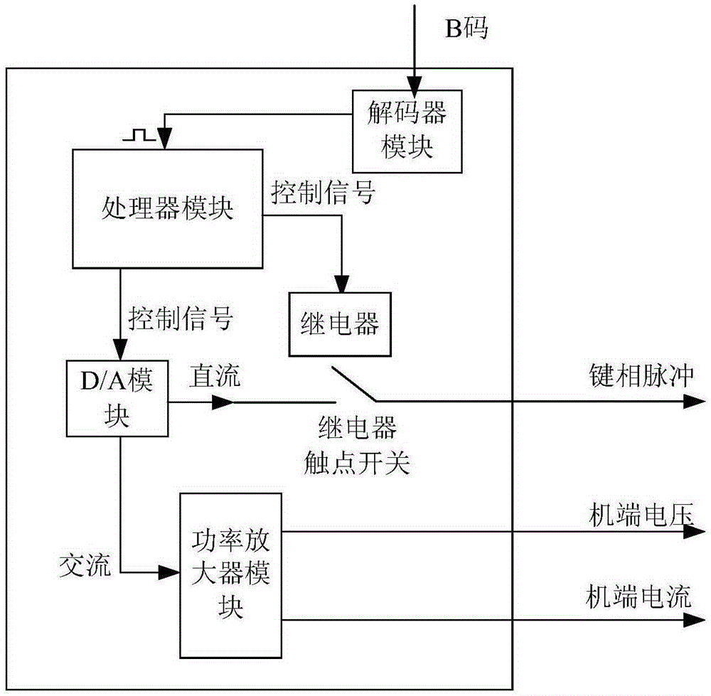
[0028] like figure 1 As shown, the embodiment of the present invention one kind tester of measuring accuracy of PMU device, comprises processor module, two-channel D / A digital-to-analog conversion module, relay module, power amplifier module and decoder module, B code timing signal The clock synchronization signal is output from the decoder module to the processor module, and the processor module outputs a D / A control signal to control one channel of the two-channel D / A digital-to-analog conversion module to output a DC voltage signal, and the other channel to output an AC voltage signal. The processor module outputs a switch control signal to control the on or off of the relay, the DC voltage signal outputs an analog key phase pulse signal through the contact switch of the relay, and the power amplifier module includes a driving power amplifier and a switching power amplifier, so The AC voltage signal is respectively amplified by the driving power amplifier to output the volt...

Embodiment 2

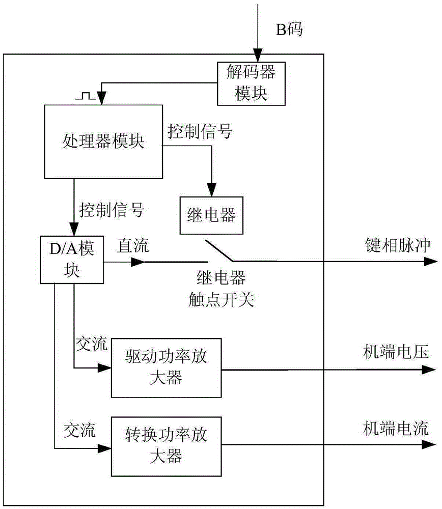
[0036] like figure 2 As shown, the difference between the second embodiment of the present invention and the first embodiment is that the D / A digital-to-analog conversion module adopts a three-channel D / A digital-to-analog conversion module, and the processor module outputs a D / A control signal to control the three-channel D / A digital One channel of the analog-to-analog conversion module outputs a DC voltage signal, the other channel outputs an AC voltage signal, and the other channel outputs an AC voltage signal. One of the two AC voltage signals is amplified by the drive power amplifier to output the analog terminal voltage signal, and the other is converted to power The amplifier converts the AC current signal and outputs the analog terminal current signal.

[0037]The three-channel D / A digital-to-analog conversion module can also use the D / A digital-to-analog conversion chip of the model DAC7744. This chip contains four independent D / A digital-to-analog conversion channel...


PUM


Abstract

The invention provides a tester for testing measurement accuracy of a PMU (Pressure Measuring Unit). The tester comprises a processor module, a D / A (Digital / Analog) conversion module, an electronic switch module, a power amplifier module and a decoder module. A B code time tick outputs a clock synchronization signal to the processor module through the decoder module; the processor module outputs a D / A control signal to control the D / A conversion module to output a direct voltage signal and an alternating voltage signal; the processor module outputs a switch control signal to control the electronic switch module to be switched on or off; the direct voltage signal outputs an analog key phase pulse signal through the electronic switch module; the power amplifier module comprises a driving power amplifier and a switching power amplifier; the alternating voltage signal is amplified through the driving power amplifier to output an analog machine end voltage signal; the analog machine end voltage signal is converted into an alternating current signal through the switching power amplifier; an analog machine end current signal is output. The invention also provides a method applying the tester to test the measurement accuracy of the PMU.

Description

technical field [0001] The invention relates to a tester and a test method for testing the measurement accuracy of a PMU device. Background technique [0002] With the continuous expansion of the grid scale, its safe operation has become an important issue in power production. Since the wide-area measurement system can realize synchronous monitoring and effective control of the entire network under dynamic conditions, it has been widely used in real-time status monitoring, disturbance recording, out-of-step protection, power grid stability control and other fields. [0003] PMU device, synchronous vector measurement device, is an important part of wide-area measurement system, mostly used in power plants and substations, real-time and continuous measurement of phasor parameters such as generator power angle, bus or line voltage amplitude, phase angle, etc. The transmission channel transmits the measured values ​​with time stamps to the monitoring center for real-time dynami...

Claims


Application Information

Patent Timeline
Patent Type & Authority Patents(China)
IPC IPC(8): G01R35/00
Inventor 汪溢马凯黄曙陈炯聪王红星侯艾君余南华包伟李晓朋谈树峰张晓悦曹丽娟冯善强胡春潮杨占杰张莹顾峰胡宝王利业凌特利
Owner ELECTRIC POWER RES INST OF GUANGDONG POWER GRID
Learn More