Splicing type unfolding device for planar antenna of aerospace craft

A technology for aerospace vehicles and planar antennas, applied in the field of aerospace vehicles, can solve the problems of non-universal spacecraft platforms, low antenna fundamental frequency, and increased antenna weight.

Active Publication Date: 2014-04-02
SHANGHAI AEROSPACE SYST ENG INST
View PDF5 Cites 19 Cited by
  • Summary
  • Abstract
  • Description
  • Claims
  • Application Information

AI Technical Summary

Problems solved by technology

[0007] The object of the present invention is to provide a splicing type deployment device for the planar antenna of an aerospace vehicle, so that the "H" configuration spacecraft platform can reduce or eliminate the antenna cantilever, and effectively solve the problem of "H" configuration plana...

Method used


Image

  • Splicing type unfolding device for planar antenna of aerospace craft
  • Splicing type unfolding device for planar antenna of aerospace craft

Examples


Embodiment Construction

[0025] The space vehicle planar antenna splicing deployment device proposed by the present invention will be further described in detail below in conjunction with the accompanying drawings and specific embodiments. Advantages and features of the present invention will be apparent from the following description and claims. It should be noted that all the drawings are in very simplified form and use imprecise ratios, which are only used for the purpose of conveniently and clearly assisting in describing the embodiments of the present invention.
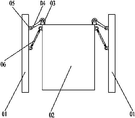
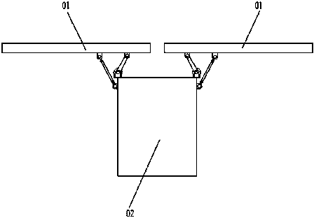
[0026] The core idea of ​​the present invention is to provide an aerospace vehicle planar antenna splicing deployment device, including a spacecraft platform, a planar antenna, a driving device, a deployment device active rod, a mounting support, and a deployment device driven rod; wherein, the plane The antenna is folded in an "H" configuration relative to the spacecraft platform, and the left and right wings of the planar antenna are ...


PUM


Abstract

The invention discloses a splicing type unfolding device for the planar antenna of an aerospace craft. The device comprises an aerospace craft platform, the planar antenna, a mounting support, driving devices mounted on the aerospace craft platform, unfolding device driving rods and unfolding device driven rods, wherein the planar antenna is arranged in an H-shaped manner relative to the aerospace craft platform in a folded state, and the left wing and the right wing of the planar antenna are symmetric about the aerospace craft platform; the unfolding device driving rods and the unfolding device driven rods are connected with the planar antenna; the driving devices drive the unfolding device driving rods, the unfolding device driven rods and the planar antenna to move, so as to enable the planar antenna to complete folding and unfolding moving processes in two manners of lateral moving and rotating, finally to reach an appointed position of an unfolded state, to rotates 90 degrees relative to the aerospace craft platform from a folded position to an unfolded position, and to laterally move for a certain distance in the direction of the aerospace craft platform. According to the splicing type unfolding device for the planar antenna of the aerospace craft, antenna cantilevers of the aerospace craft platform can be reduced or eliminated.

Description

technical field [0001] The invention relates to the technical field of aerospace vehicles, in particular to a splice-type deployment device for planar antennas of aerospace vehicles. Background technique [0002] According to the electrical performance and imaging quality and accuracy requirements of planar phased array antennas, the "H" configuration is often used when the spacecraft platform is folded. For planar antennas, this configuration makes the antenna a cantilever beam In this state, it cannot be fixed with the spacecraft platform, and the force of the antenna is bad; when the antenna is unfolded, it is necessary to ensure the seam distance between the planar antennas. In order to solve the problem that the fundamental frequency of the planar antenna is too low when the plane antenna is folded, most of the domestic and foreign aerospace vehicles currently use the following methods: [0003] (1) Compress the width between the antenna mounting surfaces on both sides...

Claims


Application Information

Patent Timeline
IPC IPC(8): H01Q1/08H01Q1/12
Inventor 李波
Owner SHANGHAI AEROSPACE SYST ENG INST
Why Eureka
Try Eureka