Wind-power generating yaw speed reducer

A deceleration device and yaw technology, which is applied in the direction of wind power generator components, wind power engines, hoisting devices, etc., can solve the unreasonable structure of wind power yaw deceleration device, high precision requirements for gear shaping and spline processing, and the first The problem of uneven force on the planetary gears and other problems can be achieved to achieve a good load equalization effect, shorten the processing cycle, and improve the overall strength.

Inactive Publication Date: 2010-02-17
JIANGSU TAILONG MACHINERY GRP CO CO LTD
View PDF0 Cites 10 Cited by
  • Summary
  • Abstract
  • Description
  • Claims
  • Application Information

AI Technical Summary

Problems solved by technology

[0005] In order to solve the unreasonable structure of the wind power generation yaw deceleration device in the prior art, when the motor input connection sleeve and the first-stage sun gear are connected by rigid interference, the first-stage planetary wheel will be unevenly stressed, which will easily lead to unbalanced load and large noise , serious wear, low service life, or when spline connection is used, the processing precision of the gear shaping spline is high, the production is difficult, and the manufacturing cost is high. The purpose of the present invention is to provide a compact structure and reasonable design. The inner teeth of the connecting sleeve and the outer teeth of the first-stage sun gear are meshed and connected to each other for transmission. The first-stage sun gear is formed at one time without secondary spline tooth processing, which is convenient to manufacture and low in production cost, and the first-stage planetary gear is evenly stressed , the wind power generation yaw reduction device with good load equalization effect, small wear and long service life

Method used


Image

  • Wind-power generating yaw speed reducer

Examples


Embodiment Construction

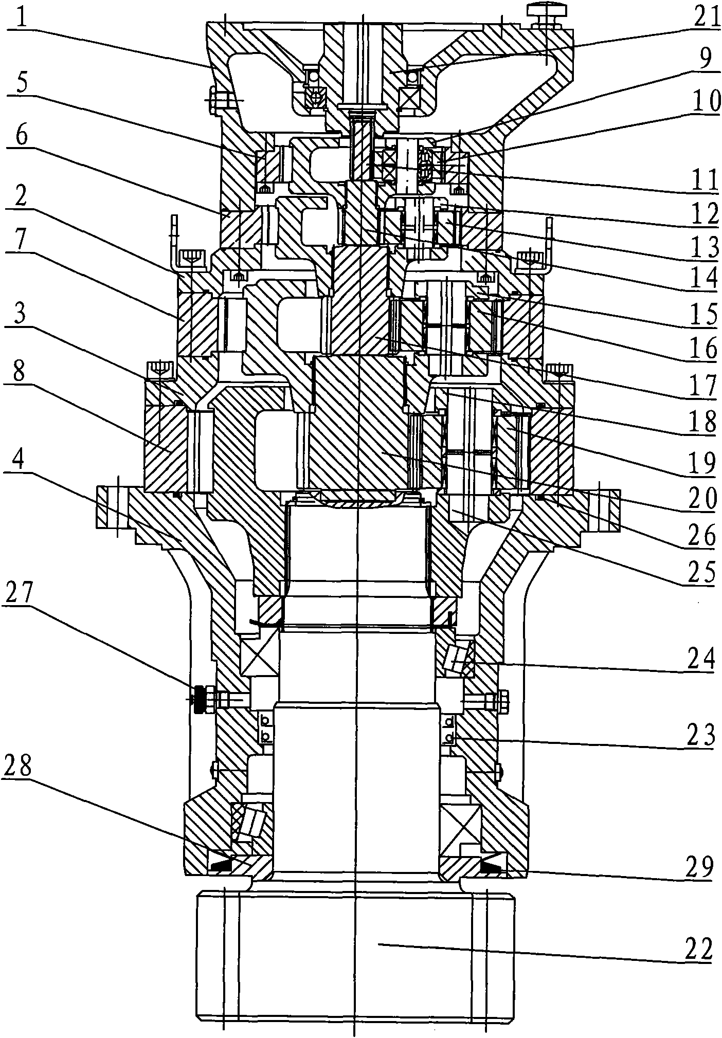
[0021] The present invention will be further described below in conjunction with the accompanying drawings and embodiments.

[0022] figure 1 As shown, the wind power generation yaw reduction device mainly includes: motor flange 1, upper box body 2, middle box body 3, support body 4, four-stage planetary transmission structure, input motor input connection sleeve 21, output gear shaft 22, oil seal Seat 28. The motor flange 1 is provided with the input motor input connection sleeve 21 and the first-stage internal ring gear 5, the first-stage internal ring gear 5 is fixedly connected in the motor flange 1 by bolts, and the connection between the motor flange 1 and the upper box body 2 The second-stage internal gear ring 6 is fixedly connected by bolts, the third-stage internal gear ring 7 is fixedly connected between the upper box body 2 and the middle box body 3 by bolts, and the middle box body 3 and the support body 4 are fixedly connected by bolts The fourth-stage internal...


PUM


Abstract

The invention relates to a yaw speed reducer of a wind power generator. Four-stage satellite transmission structures are arranged in a box and are connected with each other to be transmitted to an output gear shaft in sequence; a motor flange is connected to the upper end of the box; the output gear shaft is arranged in a support body through an upper bearing and a lower bearing and is sealed by an oil seal base; a first-stage internal gear ring is connected into the motor flange through bolts; a motor input connection sleeve is arranged in the motor flange through a bearing; the number of theinternal teeth of the motor input connection sleeve is the same as the number of the external teeth of a first-stage sun gear; and the internal teeth of the motor input connection sleeve and the external teeth of the first-stage sun gear have the same modulus and the same pressure angle of 20 degrees and are in mutual meshing transmission. The yaw speed reducer has compact structure, reasonable design, good uniform-loading effect, strong bearing and impact resistance capacity, good sealing performance and a uniformly-forced satellite gear meshed with the floating sun gear, is convenient to make and not easy to cause the environmental pollution and runs stably, thereby meeting the requirements of the clients.

Description

technical field [0001] The invention relates to a deceleration device, in particular to a yaw deceleration device suitable for wind power generation. Background technique [0002] Wind power generator is a generator driven by wind power to rotate the generator. Due to the unpredictable size and direction of wind power, it is a kind of energy with strong randomness. The impact force generated by wind power has a high uncertainty factor. For the stable operation of the unit, the wind turbine must be equipped with a yaw reduction device with strong impact resistance and a large reduction ratio. Its function is to adjust the direction of the fan by driving the yaw ring gear to achieve full use of wind resources. Effect. [0003] At present, most of the yaw gearboxes of wind turbines at home and abroad adopt multi-stage planetary gear reduction. Most of the motor input connection sleeve and the first-stage sun gear adopt rigid interference connection or spline connection. The r...

Claims


Application Information

Patent Timeline
Patent Type & Authority Applications(China)
IPC IPC(8): F03D11/00F16H1/28F16J15/16F16H55/17F03D15/00
CPCF16H1/46
Inventor 孔霞张玉圣蔡云龙
Owner JIANGSU TAILONG MACHINERY GRP CO CO LTD
Why Eureka
Try Eureka