Coaxial turbo-shaft engine

A turboshaft engine and coaxial technology, which is applied in the direction of machines/engines, mechanical equipment, gas turbine devices, etc., can solve the problems of the overall length and weight of the engine, and achieve the effects of light weight, simple support structure, and high space utilization

Inactive Publication Date: 2016-04-20
NORTHWESTERN POLYTECHNICAL UNIV
View PDF5 Cites 10 Cited by
  • Summary
  • Abstract
  • Description
  • Claims
  • Application Information

AI Technical Summary

Problems solved by technology

[0004] An embodiment of the present invention provides a coaxial turboshaft engine to at least solve the technical problem that the existing turboshaft engine adopts the series layout of the shafting connection, which leads to a relatively large overall length and weight of the engine

Method used


Image

  • Coaxial turbo-shaft engine
  • Coaxial turbo-shaft engine
  • Coaxial turbo-shaft engine

Examples


Embodiment Construction

[0020] In order to enable those skilled in the art to better understand the solutions of the present invention, the following will clearly and completely describe the technical solutions in the embodiments of the present invention in conjunction with the drawings in the embodiments of the present invention. Obviously, the described embodiments are only It is an embodiment of a part of the present invention, but not all embodiments. Based on the embodiments of the present invention, all other embodiments obtained by persons of ordinary skill in the art without making creative efforts shall fall within the protection scope of the present invention.

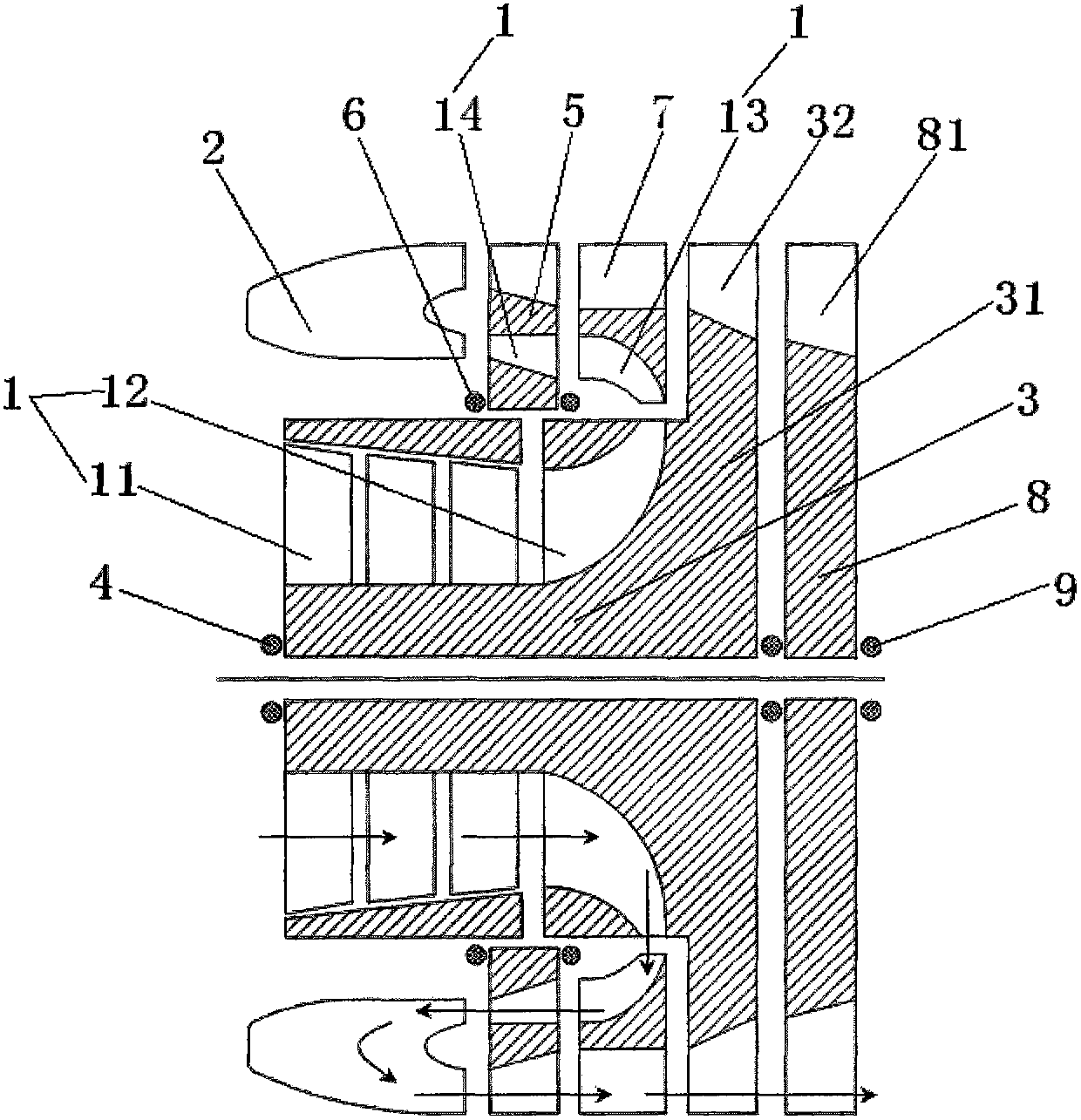
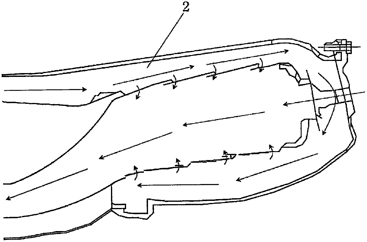
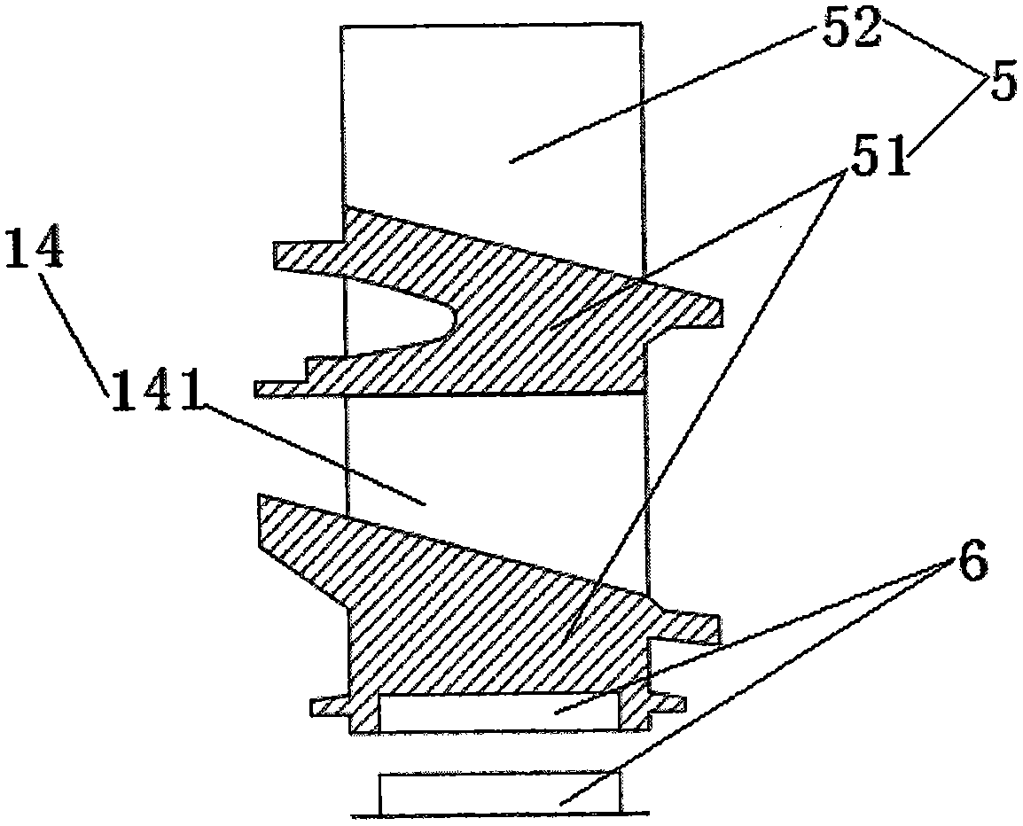
[0021] According to an embodiment of the present invention, a coaxial turboshaft engine is provided, such as figure 1 As shown, it includes: compressor 1 and combustion chamber 2, the exhaust port of compressor 1 and the intake port of compressor 1 are deflected by a preset angle so that compressor 1 forms a horizontal "U"-shaped ai...


PUM


Abstract

The invention discloses a coaxial turbo-shaft engine. An exhaust opening and an air inlet of the air compressor are deflected a preset angle so that one horizontal U-shaped air flow passage is formed in the air compressor; meanwhile, the exhaust opening and air inlet of the combustion chamber are deflected a preset angle so that one horizontal U-shaped air flow passage is formed in the combustion chamber; the air inlet of the combustion chamber is communicated with the exhaust opening of the air compressor to form an S-shaped air flow passage. Thus, the layout mode of an engine rotor structure and the layout structure for air charging and air exhausting are integrally changed. The coaxial turbo-shaft engine has the advantages of solving the technical problem that an existing turbo-shaft engine is relatively large in overall length and weight because of application of a serial-connection layout mode which adopts shaft coupling, and realizing the technical effects that the engine is short in overall length, light in mass, simple in supporting structure and high in space utilization rate.

Description

technical field [0001] The invention relates to the technical field of aeroengines, in particular to a coaxial turboshaft engine. Background technique [0002] As a main form of aeroengine, turboshaft engine has been widely used in power fields such as helicopters. In traditional turboshaft engines, rotating parts such as compressors and turbines generally use a series arrangement of rotor structure and shafting connection, and this series arrangement significantly increases the length and weight of the engine. Not only that, the shafting connection method It also caused the support system of the engine to be particularly complicated, not only working at a state close to the maximum temperature, but also bearing extreme axial force, and the working conditions were extremely harsh. At the same time, the shaft connection also puts forward high requirements on the structural strength, processing technology and installation accuracy of the shaft. More importantly, the tandem l...

Claims


Application Information

Patent Timeline
Patent Type & Authority Applications(China)
IPC IPC(8): F02K3/00F02C3/14
Inventor 杨帆周莉张晓博王占学
Owner NORTHWESTERN POLYTECHNICAL UNIV
Why Eureka
Try Eureka