
An Adaptive Differential Protection Method

A differential protection and self-adaptive technology, applied in emergency protection circuit devices, electrical components, etc., can solve the problems of the current on both sides of the line being flat and the brake differential protection refuses to act, so as to solve the possible refusal to act and improve the sensitivity. Effect

Active Publication Date: 2017-01-25
BEIJING SIFANG JIBAO AUTOMATION +1
View PDF2 Cites 0 Cited by
  • Summary
  • Abstract
  • Description
  • Claims
  • Application Information

AI Technical Summary

Problems solved by technology

[0005] In order to solve the problem that the typical proportional brake differential protection based on "phasor sum" and "phasor difference" may refuse to operate due to the angle difference of the current on both sides of the line being an obtuse angle or even a flat angle when there is an internal fault in the transmission line. The invention discloses an adaptive differential protection method

Method used


Image

  • An Adaptive Differential Protection Method
  • An Adaptive Differential Protection Method
  • An Adaptive Differential Protection Method

Examples


Embodiment Construction

[0032] The technical solutions of the present invention will be described in further detail below in conjunction with the accompanying drawings and specific examples.

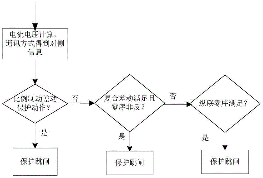
[0033] like figure 1 Shown is the flow chart of the adaptive differential protection protection method of the present invention, the adaptive differential protection method of the present invention includes the following steps (with figure 2 The schematic diagram of a typical transmission line fault is shown as an example):

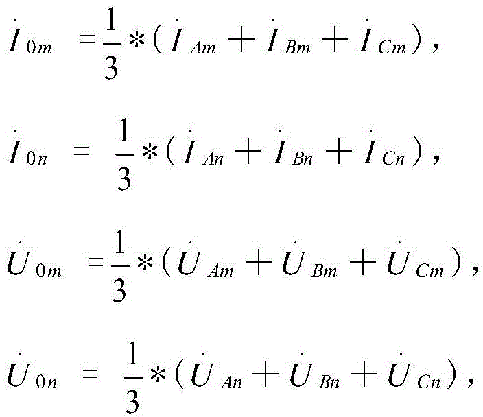
[0034] Step 1: The line protection device samples and filters the line voltage and current waveforms collected by the transformer, exchanges information such as current and voltage on both sides of the line through communication, and calculates the current on both sides of the line =A, B, C, m, n represent both sides of the line, the same below), voltage Zero sequence current Zero sequence voltage in Indicates the three phases A, B, and C of the transmission line, and m and n re...


PUM


Abstract

The invention relates to an adaptive differential protection method, which comprises the steps that a line protection device performs sampling and filtering to voltage and current waveforms of a transformer; information such as current and voltage on the two sides of a line is exchanged through communication; current I<phi m> and I<phi n> (wherein phi=A, B and C which respectively stand for three phases of the power transmission line; m and n stand for the two sides of the line, similarly hereinafter), voltage U<phi m> and U<phi n>, zero-sequence current I<0m> and I<0n> and zero-sequence voltage U<0m> and U<0n> of the two sides of the line are obtained through calculation; proportional brake differential protection, composite differential protection and longitudinal differential protection are formed; the proportional brake differential protection, the composite differential protection and the longitudinal differential protection are combined to form the adaptive differential protection. The adaptive differential protection method provided by the invention has the characteristics of high sensitivity, wide application scope and no setting. The adaptive differential protection method has the advantages that the sensitivity to short-circuiting in the original differential protection can be improved, the action can be sensitively performed when the angle difference of the system equivalent impedance of the two sides of a fault point is great (such as under the situation that current phase reversion occurs in the power transmission line with serial compensation capacitors), the quick action can be realized during oscillation and the fixed value of the original differential protection is not increased.

Description

technical field [0001] The invention belongs to the field of power systems, and more specifically relates to a method for relay protection. Background technique [0002] In EHV transmission lines, optical fiber differential protection has been widely used as the main protection. [0003] The principle of optical fiber differential protection is advanced, and the typical differential criterion is the proportional braking differential protection based on "phasor sum" and "phasor difference". (For example, the current reverse phase occurs in the transmission line containing series compensation capacitors), or when an internal fault occurs during oscillation, the current angle difference on both sides of the line is an obtuse angle or even a flat angle, which will affect the typical proportional braking differential protection criterion sensitivity. [0004] How to better improve the performance of differential protection needs to be studied. Contents of the invention [00...

Claims


Application Information

Patent Timeline
Patent Type & Authority Patents(China)
IPC IPC(8): H02H7/26
Inventor 魏会利伍叶凯杜兆强黄少锋张月品于洪雷
Owner BEIJING SIFANG JIBAO AUTOMATION
Learn More