Quasi-resonance flyback converter as well as controller thereof and control method

A flyback converter, quasi-resonance technology, applied in the direction of output power conversion devices, electrical components, etc., can solve the problem of shortening the demagnetization time

Active Publication Date: 2014-04-02
HANGZHOU SILAN MICROELECTRONICS
View PDF2 Cites 13 Cited by
  • Summary
  • Abstract
  • Description
  • Claims
  • Application Information

AI Technical Summary

Problems solved by technology

However, as the power demand decreases, the demagnetization time of the transformer 101 is shortened, and when the demagnetization time is shortened below 8 μs, the frequency is clamped

Method used


Image

  • Quasi-resonance flyback converter as well as controller thereof and control method
  • Quasi-resonance flyback converter as well as controller thereof and control method
  • Quasi-resonance flyback converter as well as controller thereof and control method

Examples


Embodiment Construction

[0039] The present invention will be further described below in conjunction with specific embodiments and accompanying drawings, but the protection scope of the present invention should not be limited thereby. For ease of understanding, the specific implementation and application of quasi-resonant technology with valley locking logic in quasi-resonant control is analyzed.

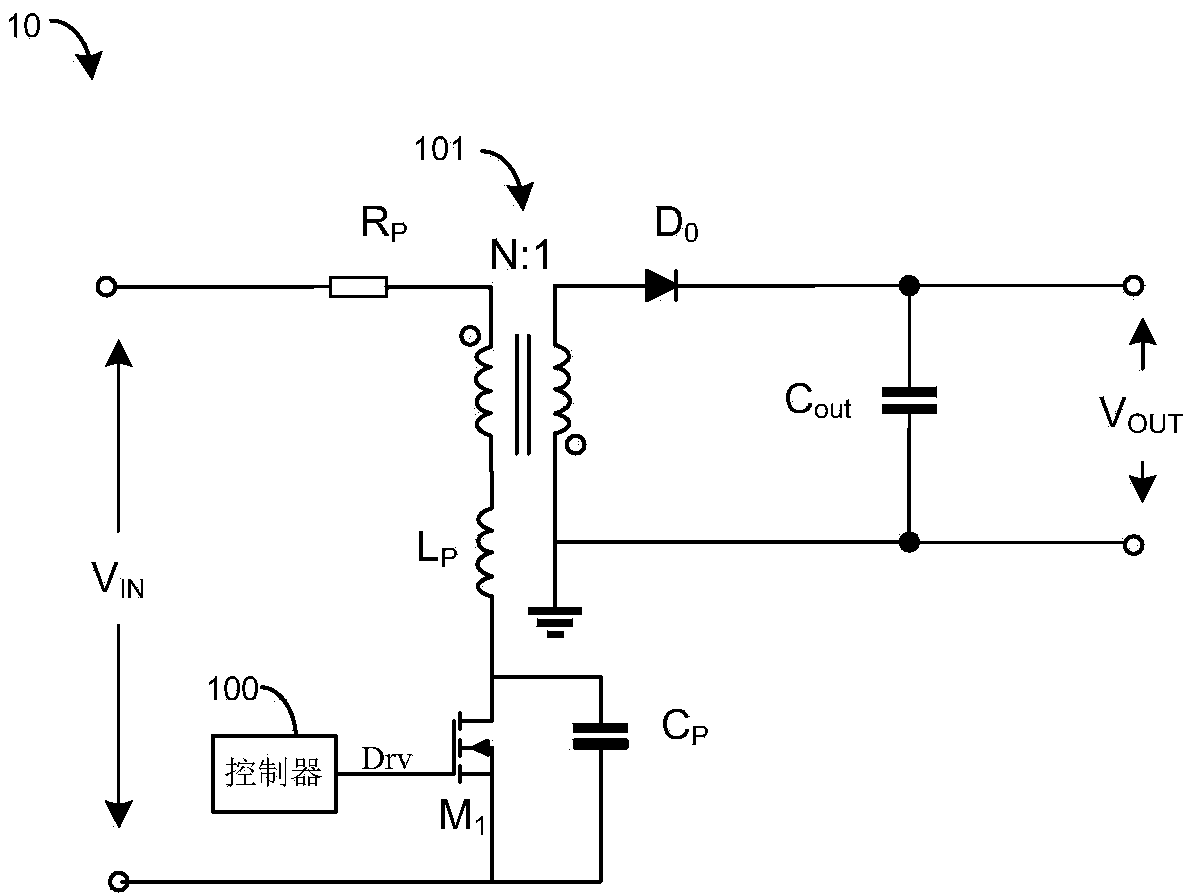
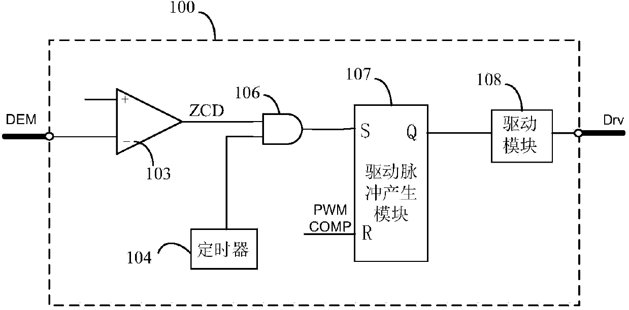
[0040] Figure 2A It is an internal structure diagram of the controller 200 of the quasi-resonant flyback converter according to an embodiment of the present invention. The controller 200 can be applied as Figure 1A quasi-resonant flyback converter shown in and replace the Figure 1A The controller 100 shown in. Those skilled in the art can understand that the controller 200 can be applied to other forms of quasi-resonant flyback converters, and is not limited to Figure 1A The specific implementation shown in . For ease of understanding, the following will combine Figure 1A with Figure 2A to describe...


PUM


Abstract

The invention discloses a quasi-resonance flyback converter as well as a controller thereof and a control method. The invention provides a controller for a quasi-resonance flyback converter. The quasi-resonance flyback converter comprises a switch tube for controlling the input voltage. The controller comprises a zero-cross detection comparator, a valley bottom locking logic circuit and a driving pulse generation module, wherein the zero-cross detection comparator is used for detecting the oscillation voltage generated by the quasi-resonance flyback converter after the switch tube is turned off and generating a valley detection signal when the valley bottom oscillation voltage is detected; the valley bottom locking logic circuit is used for counting valley bottoms of the valley bottom detection signal and transmitting a valid valley bottom signal when a selected valley bottoms appear; the driving pulse generation module is used for transmitting a triggering signal to conduct connect the switch tube under the instruction of the valid valley bottom signal.

Description

technical field [0001] The invention relates to a quasi-resonance (QR) technology in a power management circuit, in particular to a quasi-resonance flyback converter and its controller and control method. Background technique [0002] The application of power management circuits is very extensive. Most power management circuits require built-in or external MOSFETs. By detecting the current value flowing through the MOSFETs, a voltage signal or current signal related to the current value can be obtained, and then according to the voltage signal or Current signal to control the MOSFET on and off. [0003] Quasi-resonant (QR) flyback converters are widely used. The main feature of this architecture is the ability to achieve zero-voltage turn-on (ZVS) operation, which can effectively reduce switching losses and help weaken electromagnetic interference (EMI) signals. Figure 1A is a schematic diagram of a quasi-resonant flyback converter 10, which may include a resistor R P , t...

Claims


Application Information

Patent Timeline
Patent Type & Authority Applications(China)
IPC IPC(8): H02M1/44
Inventor 高阳
Owner HANGZHOU SILAN MICROELECTRONICS
Why Eureka
Try Eureka