Composite milling cutter

A technology for milling cutters and slot milling cutters, applied in milling cutters, milling machine equipment, manufacturing tools, etc., can solve the problems of easy chipping, easy to cause waste, and large overall damage.

Inactive Publication Date: 2014-04-09
李仕清
View PDF4 Cites 4 Cited by
  • Summary
  • Abstract
  • Description
  • Claims
  • Application Information

AI Technical Summary

Problems solved by technology

[0002] At present, milling cutters used in mechanical processing are composed of cutting blades or cutting cutter bodies or tool holders or positioning holes. The cutting edge of the milling cutter has a single force in the feed direction, that is, a single force on one cutting edge The curved or straight shape of the cut

Method used


Image

  • Composite milling cutter
  • Composite milling cutter
  • Composite milling cutter

Examples


Embodiment approach 1

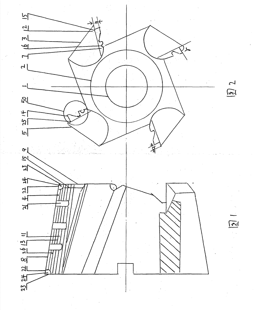
[0035] Such as Figure 1-2 , Figure 35-Figure 42 As shown, the compound milling cutter according to the first embodiment of the present invention, in particular, relates to various compound shell end mills, including a tool shank or a positioning hole 1 and a tool head 2, the tool shank or positioning hole 1 and a tool head 2 connected or formed as one, the tool head 2 is integrally provided with a plurality of cutting blades or cutting blade bodies 3, on the cutting surface 4 of each cutting blade or cutting blade body 3, the direction of the cutting surface 4 facing the cutting direction The rear side or the back side is a rear cutting surface 5 or a side cutting surface 7, and the cutting surface 4 intersects with the rear cutting surface 5 or the side cutting surface 7 to form at least one cutting edge 8, or at least one side cutting edge 9, the composite Milling cutters involve various concave and convex semicircular milling cutters, or various keyway milling cutters, or...

Embodiment approach 2

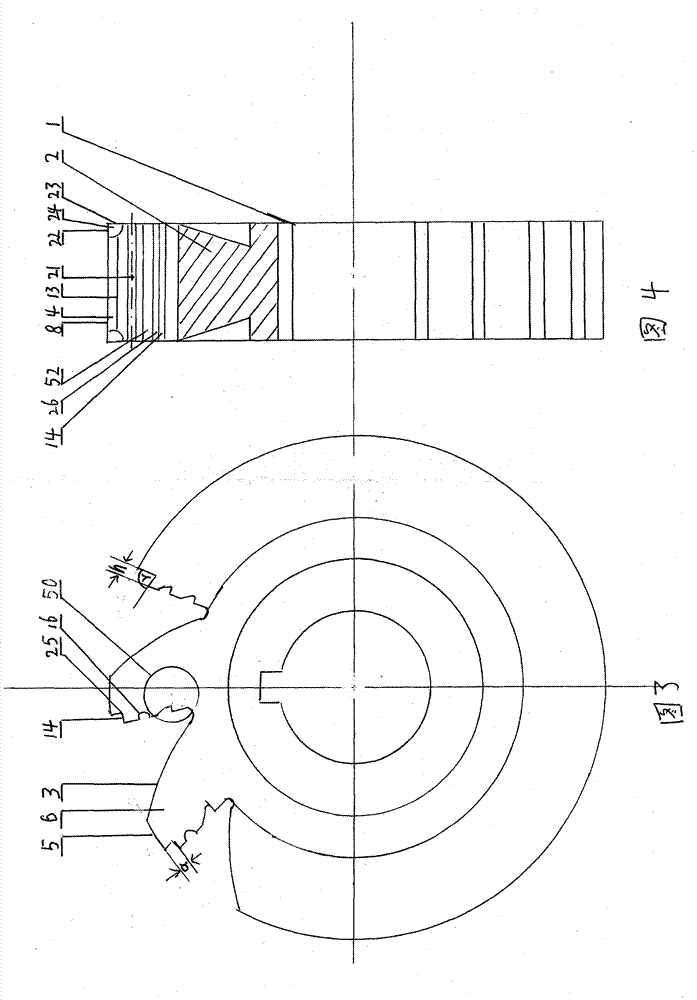
[0038] Such as Figure 3-4 , Figure 35-Figure 42 As shown, the compound milling cutter of the second embodiment of the present invention, specifically relates to various compound saw blade milling cutters, on the basis of the effect of the first embodiment, the present invention includes a positioning hole 1 and a cutter head 2, the cutter The shank or positioning hole 1 and the cutter head 2 are integrally formed, and the cutter head 2 is integrally provided with a plurality of cutting blades or cutting blade bodies 3, and each cutting blade or cutting blade body 3 has a cutting surface 4. The rear side or back side of the cutting surface 4 in the cutting direction is the rear cutting surface 5, or the side cutting surface 6, or the secondary cutting surface 7, and the cutting surface 4 intersects the rear cutting surface 5 or the side cutting surface 7, forming at least one cutting surface. Edge 8, or at least one side cutting edge 9, towards the inboard of the cutting sur...

Embodiment approach 3

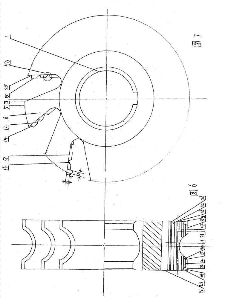
[0040] Such as Figure 5 Figure 16 , Figure 35-Figure 42 As shown, the compound milling cutter of the third embodiment of the present invention, specifically relates to various compound dovetail grooves or compound reverse dovetail groove milling cutters, on the basis of the effects of the first and second embodiments, the present invention includes positioning holes 1 and a cutter head 2, the tool handle or positioning hole 1 and the cutter head 2 are integrally formed, and the cutter head 2 is integrally provided with a plurality of cutting blades or cutting blade bodies 3, and each cutting blade or cutting blade body 3 There is a cutting surface 4, the back side or back side of the cutting surface 4 facing the cutting direction is the rear cutting surface 5, or the side cutting surface 6, or the secondary cutting surface 7, the cutting surface 4 and the rear cutting surface 5 or the side cutting surface 7 intersect, forming at least one cutting edge 8, or at least one s...


PUM


Abstract

The invention provides a composite milling cutter. The composite milling cutter is high in efficiency and strength, and long in service life, and is provided with a cutter handle or a locating hole and a cutter head. The composite milling cutter is characterized in that: on a cutting face arrange toward the helix direction, a triangle groove or a trapezoid-shaped groove, or an arc triangle groove or an arc trapezoid-shaped groove is arranged, or an arc-shaped convex, or an inclined convex and concave is arranged, and at least one grade bottom or side part is provided, a plurality of internal inclined cutting faces arranged with an angle more than 90 DEG and less than 180 DEG with the helix cutting face are provided, or a plurality of composite helix cutting faces; or extending of the arc-shaped convex or the inclined convex forms a compound locating resolution platform which is connected with an internal composite helix cutting face, forms a plurality of internal inclined blades or side concave blades, or side inclined blades, so that cutting stress is inclined toward inside, force arm is reduced, outside cutting resistance is resolved, cutting efficiency and service life of the composite milling cutter are increased and prolonged to a largest value respectively, cost is reduced, and resources are saved.

Description

Technical field: [0001] The present invention relates to a compound milling cutter, which is used in mechanical processing of milling machines and the like. Background technique: [0002] At present, milling cutters used in mechanical processing are composed of cutting blades or cutting cutter bodies or tool holders or positioning holes. The cutting edge of the milling cutter has a single force in the feed direction, that is, a single force on one cutting edge The curved or straight shape of the cutting edge is composed of a single cutting edge. The cutting method of this cutting edge has a large resistance, resulting in a large overall destructiveness, so it is prone to chipping and accidents, and it is easy to cause waste products, which brings a lot of damage. Big losses, more serious even cause casualties. Invention content: [0003] The present invention is proposed in view of the above-mentioned problems, and aims to provide a new type of compound milling cutter, wh...

Claims


Application Information

Patent Timeline
IPC IPC(8): B23C5/02
Inventor 李仕清
Owner 李仕清
Why Eureka
Try Eureka